MKS 937B Operation Manual
66
In applications where the system may be exposed to large voltage fluctuations, a centering ring with a
screen should be installed, and the screen and tubing grounded. The clamp must be tightened
properly so that the flange contacts the centering ring.
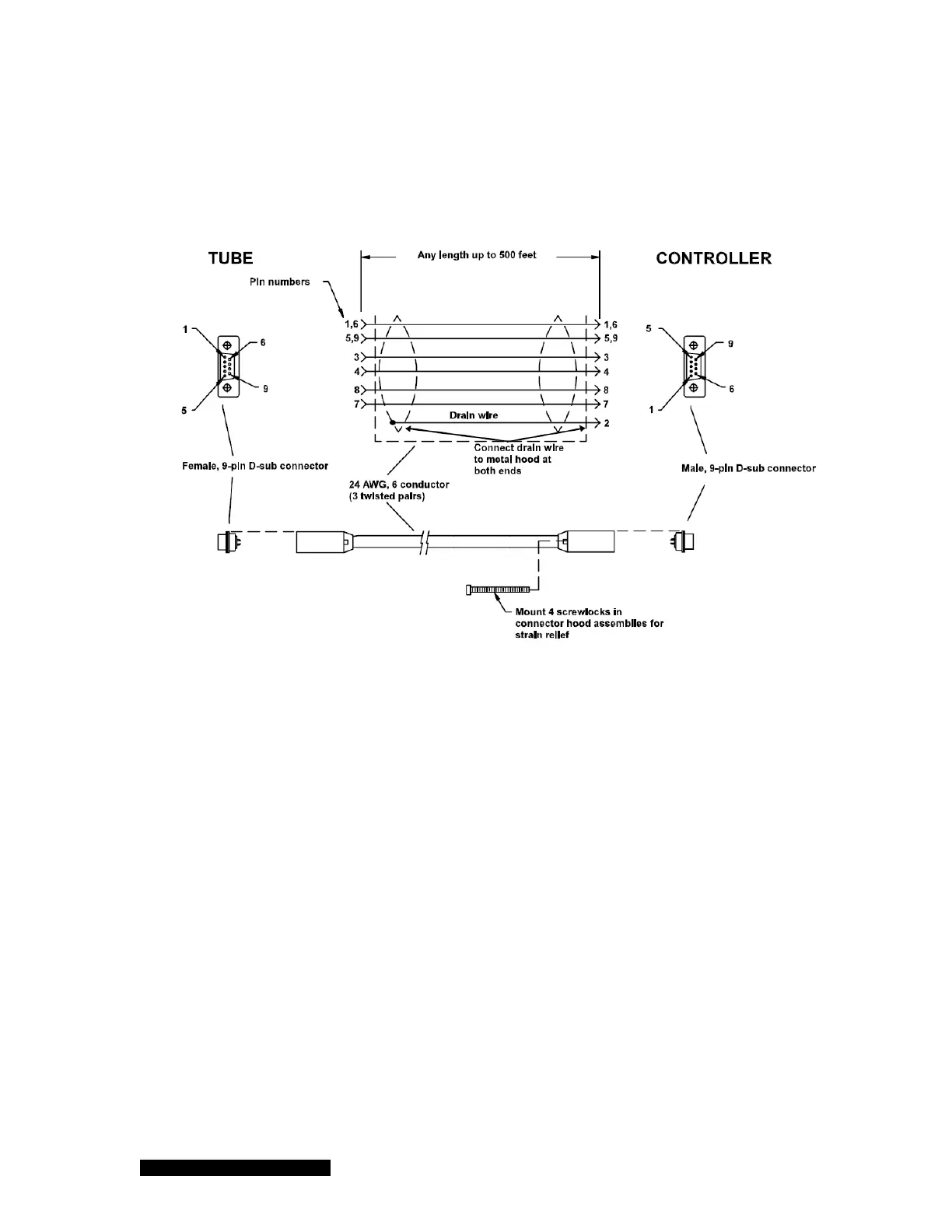
The sensor cable is connected to the 937B Controller with the 9-pin "D" connector as shown in Figure
7-4. This connector is equipped with integral strain relief. Screw the strain relief into the mating
standoffs on the rear of the Controller for good contact and to avoid excess stress on the connectors.
Figure 7-4 317/345 cable diagram.
If excess stress is applied to the cable, use separate strain relief to prevent damage to the sensor,
cable or the Controller. Cables are available from HPS in standard lengths of 10, 25, 50, and 100
feet and in custom lengths up to 500 feet.
Some applications, (i.e those in which the connection is routed through restrictive barriers or a
conduit) may require the use of special cables. Custom cables may be fabricated for these situations
using the information provided below. The maximum length of the sensor cable is 500 feet. Use a "D"
connector with integral strain relief for all applications.
7.3.6 Preparing the 317 Sensor for Bakeout
Remove the cable from the Sensor. Using a #1 Phillips screwdriver, remove the two screws at the
end of the connector/electronics subassembly separating it from the Sensor. The standard
Convection Pirani Sensor can be baked up to 150°C and the Shielded Convection Pirani Sensor can
be baked up to 100°C. A new 317 with aluminum housing RF shielding can be baked to 250°C.

 Loading...


