MKS 937B Operation Manual
64
LPN Ground No Connection
Mini BA No Connection Ground
Glass BA Ground Ground
UHV-24 No Connection No Connection
Table 7-2 Pin assignment for HC sensor type identification.
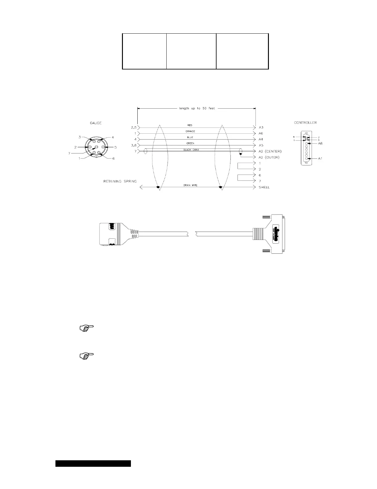
Figure 7-2 LPN gauge cable diagram.
Figure 7-3 Mini BA gauge cable diagram.
When exerting force on the cable, use a separate strain relief to prevent damage to the sensor or
controller. Cables are available in standard lengths of 10, 25 & 50 feet only. Connect the cable to the
rear of the controller at the sensor module port labeled “Hot Cathode”. Tighten the cable jackscrews
into the mating screw locks to ensure proper electrical connection and prevent stress on the
connector.
Remove power from the controller before connecting or disconnecting the cable
from the sensor or controller.
Hot cathode cables have several special characteristics, including lethal
voltages, therefore only cables supplied by HPS
®
Products should be used.