MKS 937B Operation Manual
68
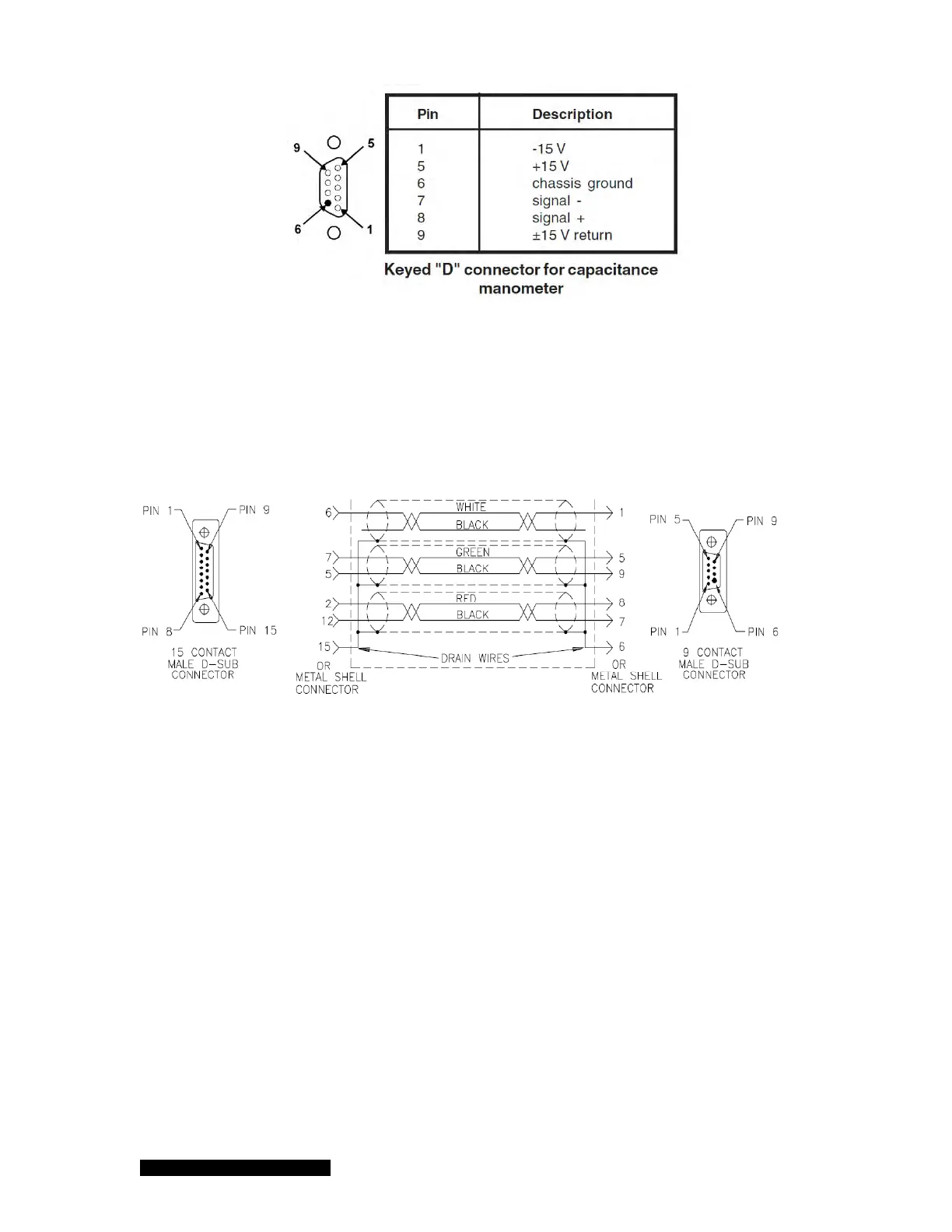
Table 7-4 Pin out of the 9 pin D-Sub connector on CM module.
A shielded cable with 9 pin male Dsub on the controller end and a 15 pin male Dsub end on the
Baratron end is required to connect the Baratron to the module on the 937B controller. Detailed
wiring for the cable is shown in Figure 7-5.
Figure 7-5 The wiring diagram for the Capacitance Manometer cable.
Controller
Baratron