MKS 937B Operation Manual
49
4. Repeat this procedure as often as necessary.
6.8 Channel Setup for Flow Measurement and Control
The 937B controller can also be used to operate MKS mass flow controllers. Up to six MFCs can be
simultaneously controlled by one 937B. The MFCs can also be used to control the system pressure.
6.8.1 Setup of a single MFC for flow or pressure control
Flow or pressure control using a single MFC can be achieved by moving the green LED indicator to
the desired MFC channel. The MFC setup information screen can be displayed when
Channel
Setup
is
pressed.
MFCs work in units of sccm only and have a control signal input voltage range of –1 to
5 V.
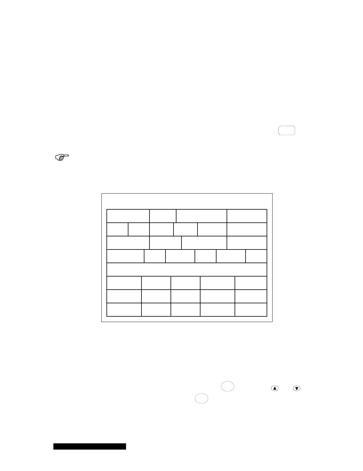
Refer to Figure 6-12 for setup for flow or pressure control:
Setup FC C1
Scale Factor
FD
Relay
Relay 02
Relay 01
Enable Dir/Ch SET SP
ABOVE
Hyst
ON 3.00E+1 2.70E+1
BELOWOFF 8.00E+2 8.80E+2
Zero NO
FlowRate SP 2.00E+2
1.00E+3Nominal Range1.00
OP Mode Setpoint
OFF
NO
PID Ctrl OFFEditR1Recipe
Range 1.40E+3
Figure 6-12 MFC setup information displayed on 937B LCD screen.
1. Scale Factor
Scale Factor is the gas correction factor ratio between the operating gas and the
factory calibration gas. If the factory calibration gas is nitrogen, the Scale Factor is
identical to the gas correction factor. Typical gas correction factor values are listed in
the Appendix 14.2 in this manual.
Move the cursor to the Scale Factor box, press
Enter
, and use the and keys
to select the correct value, and press
Enter
one more time to save the value. The
valid range is 0.1 to 10, with a default setting of 1.00.
2. Nominal Range