MKS 937B Operation Manual
97
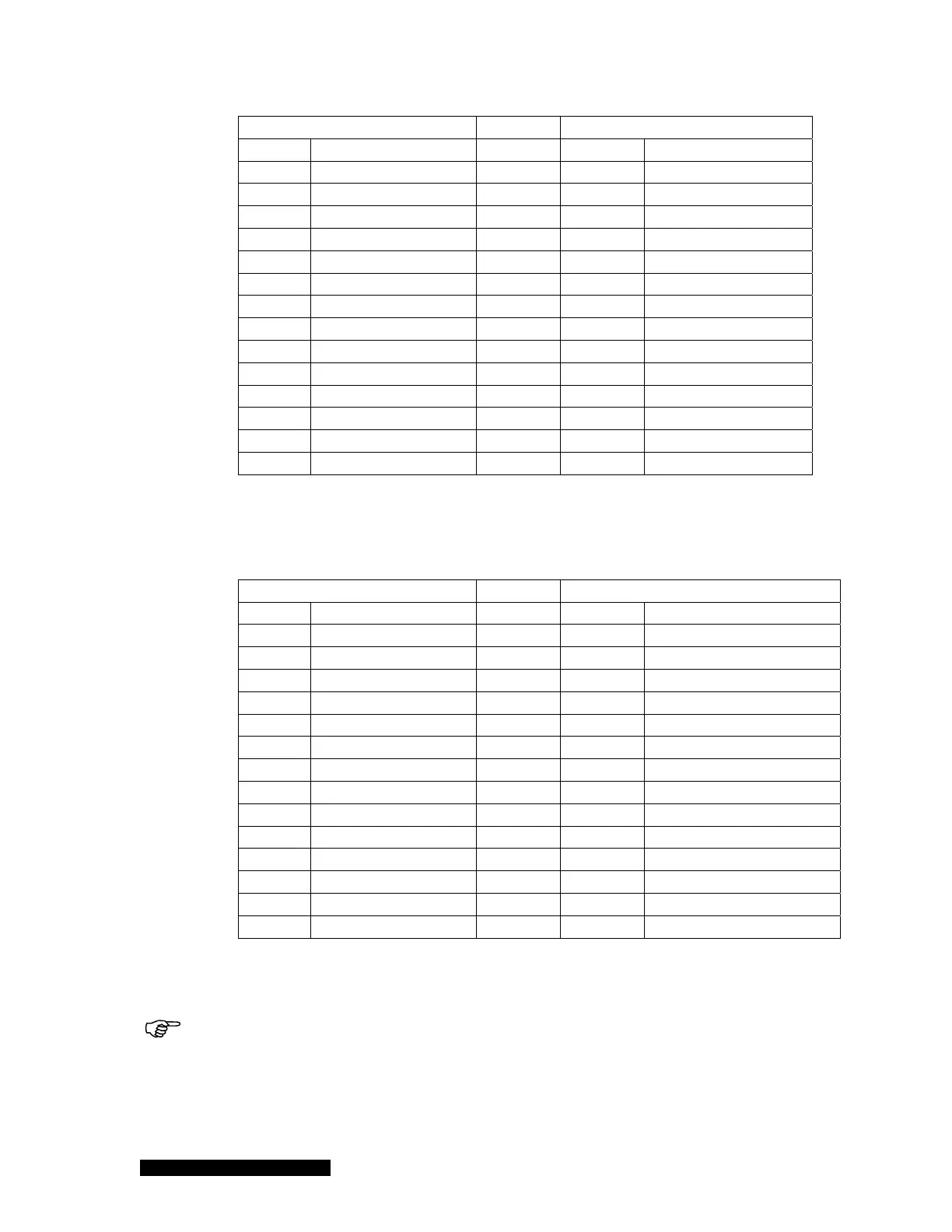
937B (37pin Dsub)
937A (25pin Dsub)
Pin Description Pin Description
1 Buffered Aout A1
2 Buffered Aout, CC
3 Buffered Aout B1
3 Buffered Aout, A1
4 Buffered Aout B2
4 Buffered Aout, A2
5 Buffered Aout C1
5 Buffered Aout, B1
6 Buffered Aout C2
6 Buffered Aout, B2
7 Log Aout A1
7 Log Aout, CC
9 Log Aout B1
8 Log Aout, A1
10 Log Aout B2
9 Log Aout, A2
11 Log Aout C1
10 Log Aout, B1
12 Log Aout C2
11 Log Aout, B2
13 Combination Aout 1
1 Combination, CC
15 Ion Gauge ON A1
13 CC disable
21-37 Ground
14-24 Ground
21-37 Ground
25 CC disable return
Table 10-2 A description of the pin assignments for adapting the 937A 25 pin connector to
the 937B 37 pin connector for analog output and gauge control when a dual PR/CM board is
installed in slot A.
937B (37pin Dsub)
937A (25pin Dsub)
Pin Description Pin Description
1 Buffered Aout A1
2 Buffered Aout, CC
3 Buffered Aout B1
3 Buffered Aout, A1
4 Buffered Aout B2
4 Buffered Aout, A2
5 Buffered Aout C1
5 Buffered Aout, B1
6 Buffered Aout C2
6 Buffered Aout, B2
7 Log Aout A1
7 Log Aout, CC
9 Log Aout B1
8 Log Aout, A1
11 Log Aout C1
10 Log Aout, B1
12 Log Aout C2
11 Log Aout, B2
13 Combination Aout 1
1 Combination, CC/B1
14 Combination Aout 2
9 Combination A/B2
15 Ion Gauge ON A1
13 CC disable
21-37 Ground
14-24 Ground
21-37 Ground
25 CC disable return
Table 10-3 A description of the pin assignments for adapting the 937A 25 pin connector to
the 937B 37 pin connector for analog output and gauge control when a CC board is installed in
slot A.
When setting the 937B to 937A operation mode, the old 937A communication cable has
to be re-wired. Ddetails are shown in Table 10-3