9-11
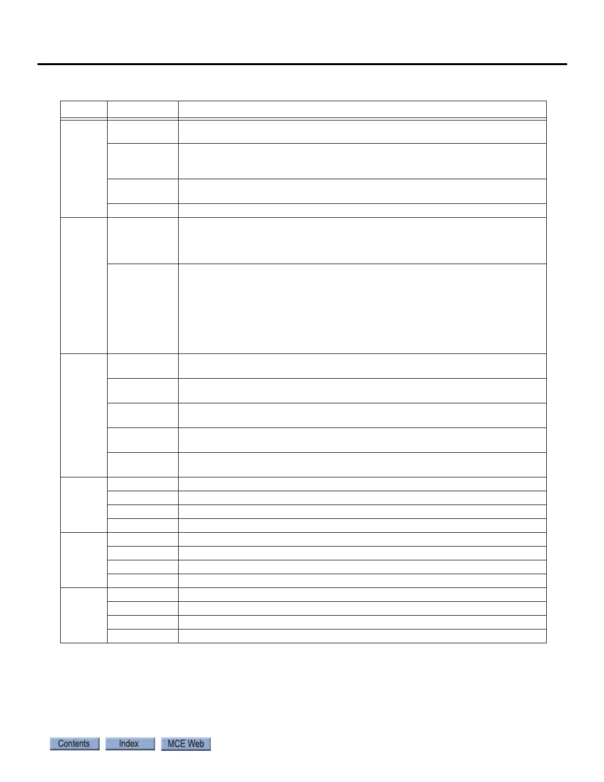
iBox Field Connections
iControl AC
9
DRIVE
MD Motor Drive relay indicator. When the MD relay on the iBox IRB board is closed to
enable the motor, this LED will light. Monitored by Safety Processor A.
TM Motor Triac active indicator. When the motor triac on the iBox IRB board is active
(completes circuit for MD relay), this LED will light. Monitored by Safety Processor
B.
MRD Motor Redundancy indicator. This LED lights when the main motor contactor drops
out.
MDRD Motor Drive Redundancy indicator. This LED lights when the MD relay drops out.
SAFETY
SAFC Safety Cartop input. Cartop safety relays and switches are wired in series
between SAFH (Safety Hoistway) and SAFC. If any contact in the safety string
opens, there will be 0 VDC on this input and the car will not run. If all safety con-
tacts in the string are closed, there will be 110 VDC on this input.
SAFH Safety Hoistway input. Hoistway safety relays and switches are wired in series
between the #3 bus and SAFH. The path also includes the Governor switch, with
the GOV connection providing access to the #3 bus via the governor switch. (#3
to GOV through governor switch, GOV to SAFH through hoistway safety relays
and switches). The job prints for the job provide specific wiring instructions. If
any contact in the safety string opens, there will be 0 VDC on this input and the
car will not run. If all safety contacts in the string are closed, there will be 110
VDC on this input.
SPARES
SP1 D Optional input. Job prints will show if and how this is used on a per installation
basis.
SP2 D Optional Brake Pick switch input. When brake is set = 110 VDC. When brake is
picked (brake pick switch open) = 0 VDC.
SP2 Optional input. Job prints will show if and how this is used on a per installation
basis.
SP3 Optional input. Job prints will show if and how this is used on a per installation
basis.
SP4 Optional input. Job prints will show if and how this is used on a per installation
basis.
COMMON
1 Common Bus connections. 0 V
1 Common Bus connections. 0 V
1 Common Bus connections. 0 V
1 Common Bus connections. 0 V
120 VAC
2 PI 120 VAC. Fused, 2PI.
2 PI 120 VAC. Fused, 2PI.
2 120 VAC. Fused, F2.
2 120 VAC. Fused, F2.
110 VDC
3 HA 110 VDC. Fused, F3HA.
3 HA 110 VDC. Fused, F3HA.
3 110 VDC. Fused, F3.
3 110 VDC. Fused, F3.
Table 9.3 iBox Field Connections
Source Connection Signal Description