9-12 Manual # 42-02-2223
Reference
Field connections are also made to terminal strips in the iControl cabinet. Terminal connec-
tions provided vary from job to job depending upon need. Power distribution connections,
beyond the basic three system buses, are specified in the job prints and are not included here.
System and LAN Ethernet
Communication between iControl elevator controllers and iCentral group control uses Ethernet
TCP/IP (Transmission Control Protocol/Internet Protocol) over the System network. Commu-
nication between iControl elevator controllers and/or the iCentral group control and personal
computers running iView or other iControl applications is over the LAN (Local Area Network)
network. Cables used in the two systems are color-coded for easy recognition. System cables
are orange. LAN cables are blue.
The following tables provide in-depth addressing information for the iControl/iCentral system.
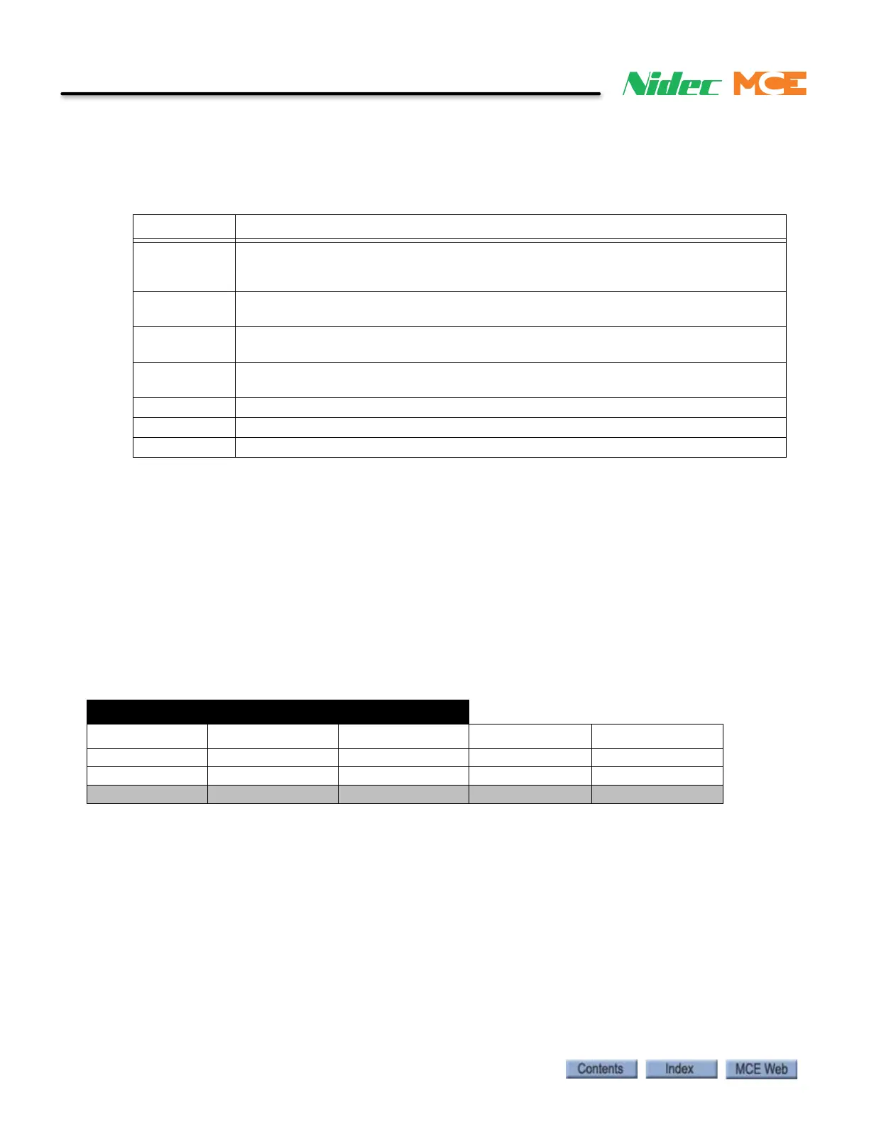
MCE Direct-Connect Port (Links one iBox to one Laptop with iView)
Table 9.4 Controller Terminal Strip Connections
Label Signal Description
B1, B2 DC power to motor brake. Voltage across terminals will vary depending upon brake
control method (Low Current Brake Board or iField Brake Module). See your job
prints. Significant voltage may be present even when brake is not picked.
MF1, MF2 DC power to motor field. Voltage across terminals will vary. Significant voltage may
be present even if motor is not running.
15A Final Limit switch. Wired as shown in job prints. 110 VDC when switch is made. 0
VDC when switch in string opens.
15B Pit/Final Limit switch. Wired as shown in job prints. 110 VDC when switch is made. 0
VDC when switch in string opens.
1 System common.
2 120 VAC bus.
3110 VDC bus.
IBox Direct Connect Port
“= same as above
IP Subnet Gateway DNS
Any iBox 192.168.193.1 255.255.255.0 Blank or 0.0.0.0 Blank or 0.0.0.0
Any PC / Laptop 192.168.193.2 “ “ “
(MCE reserved) All other addresses “ “ “