9-59
Magnetek Quattro AC Quick Reference
iControl AC
9
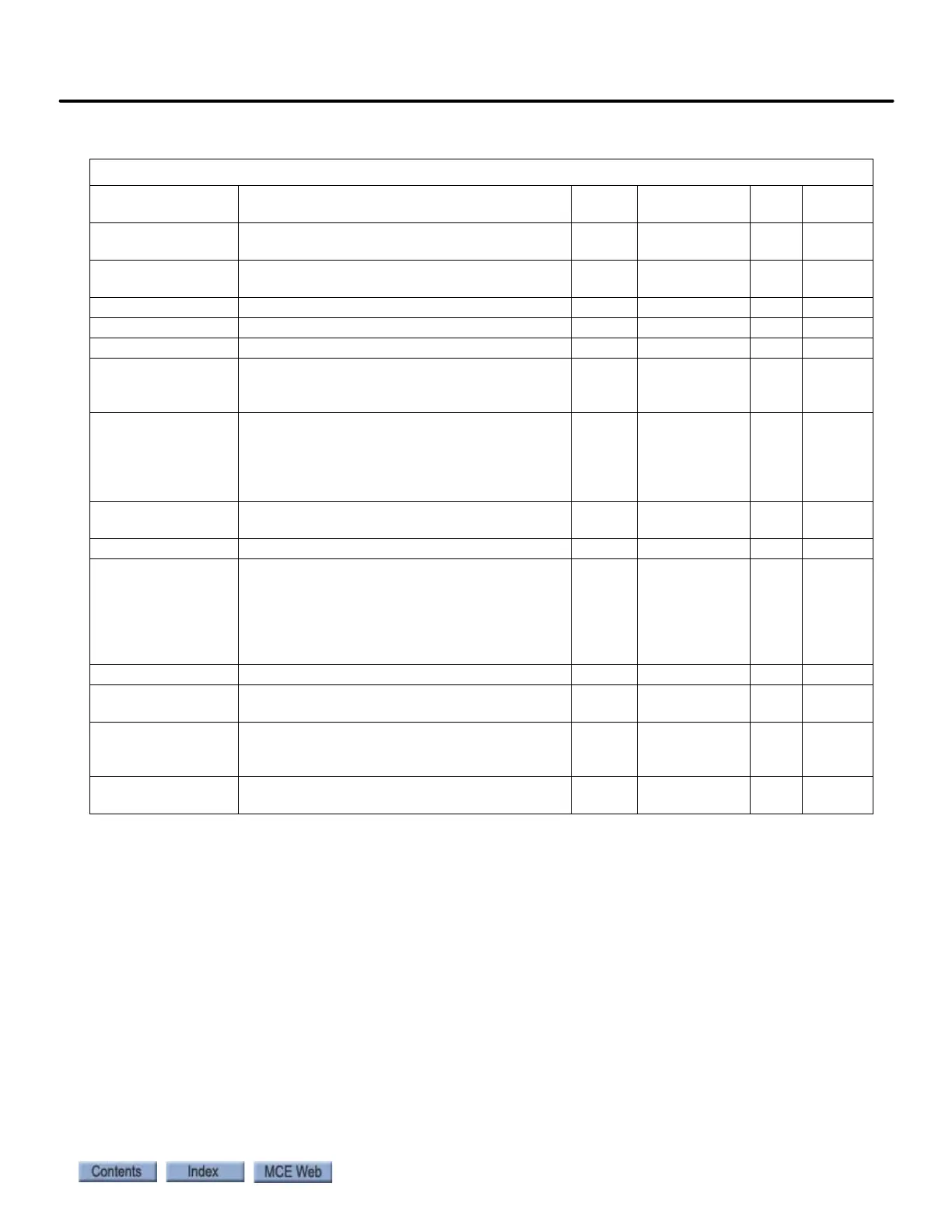
A5 Line Side Power Convert submenu
LS Id REG P GAIN Proportional gain, out of phase current regula-
tor.
None 0.00 – 9.99 0.30 0.30
LS Id REG I GAIN Internal gain for out of phase current regula-
tor.
None 0 – 999 10 10
LS Iq REG P GAIN Proportional gain for in phase current regula-
tor.
None 0.00 – 9.99 0.30 0.30
LS lq REG I GAIN Integral gain for in phase current regulator. None 0 – 999 40 40
DC BUS REG P GAIN Proportional gain for bus voltage regulator. None 0 – 9.00 3.00 3.00
DC BUS REG I GAIN Integral gain for bus voltage regulator. None 0 – 999 40 40
INPUT L-L VOLTS Input Line to Line Voltage: Must be set cor-
rectly to calibrate DC Bus voltage regulation
and pre-charge
volts 150 – 552 480 *
INITIAL L FREQ Initial Line Freq sets initial freq of input line
voltage. Default 55Hz for most applications.
But, when line power switched from utility to
emergency, should be set to actual line power
input frequency.
Hz 50 – 60 55 55
DC BUS V BOOST DC Bus voltage reference adjusts the DC bus
voltage boost above the peak of line voltage
volts 15 – 75 30 30
SW BUS OV LEVEL Software Bus overvoltage level trip point volts 100 – 850 850 850
BUS VREF SOURCE Bus voltage reference source. Selects bus volt-
age boost reference:
Track Line V uses actual line voltage for bus
reference. Recommended for a still line.
Trk Vin Param uses INPUT L-L VOLTS for bus
reference. Recommended for a soft line.
none − track line v −
trk vin param
TRACK
LINE V
TRACK
LINE V
PLL FILTER FC Phase Lock Loop Filter frequency Hz 20.0 – 150.0 40.0 40.0
POLE FILTER Pole Filter setting. Adds a low pass filter to the
line side to help alleviate nuisance noise issue
kHz 0.1 – 3.0 2.2 2.2
PRE CHGE THRESH Pre charge threshold. Determines allowable
variance between actual and calculated bus
voltage during power up
none 1 – 60 28 28
LS PWM FRE-
QUENCY
Line Side PWM freq. Sets PWM of “carrier” freq
of converter portion of drive.
kHz 8.0 – 12.0 10.0 10.0
Table 10. Quattro PM Elevator Drive, iControl