Motorola Solutions AP-6511 Access Point System Reference Guide
7-8
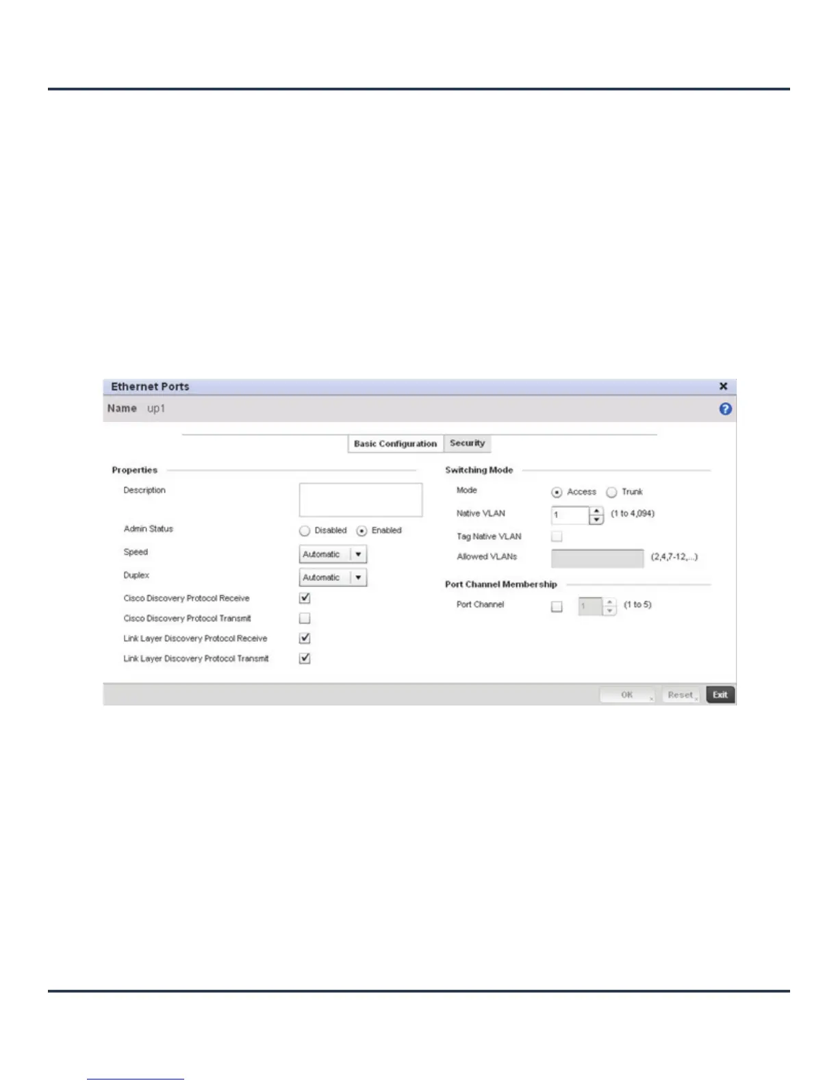
5. To edit the configuration of an existing port, select it from amongst those displayed and select the Edit
button. The Ethernet port Basic Configuration screen displays by default.
Figure 7-4 Ethernet Ports - Basic Configuration screen
6. Set the following Ethernet port Properties:
Tag Native VLAN A green checkmark defines the native VLAN as tagged. A red “X” defines the
native VLAN as untagged. When a frame is tagged, the 12 bit frame VLAN ID
is added to the 802.1Q header so upstream Ethernet devices know which VLAN
ID the frame belongs to. The device reads the 12 bit VLAN ID and forwards the
frame to the appropriate VLAN. When a frame is received with no 802.1Q
header, the upstream device classifies the frame using the default or native
VLAN assigned to the Trunk port. A native VLAN allows an Ethernet device to
associate untagged frames to a VLAN when no 802.1Q frame is included in the
frame.
Allowed VLANs Displays the VLANs allowed to send packets over the listed port. Allowed
VLANs are only listed when the mode has been set to Trunk.
Description Enter a brief description for the port (64 characters maximum). The description
should reflect the port’s intended function to differentiate it from others with
similar configurations.
Admin Status Select the Enabled radio button to define this port as active to the profile it
supports. Select the Disabled radio button to disable this physical port in the
profile. It can be activated at any future time when needed.
 Loading...