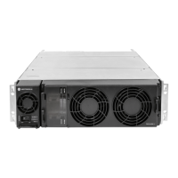
GTR8000BaseRadio
1Wearanelectrostaticdischarge(ESD)strapandconnectitscabletoaveriedgoodground.Besuretowearthis
strapthroughoutthisproceduretopreventESDdamagetoanycomponents.
2Ifthebaseradioisnotoperational,skiptostep4.
3Disablethebaseradiowiththebackplanebeingreplace,sothesystemdoesnotattributethelossofchannel
toafailure.
a.ConnecttothedevicemodulesEthernetserviceportusingConguration/ServiceSoftware(CSS).See4.4.4
ConnectingThroughanEthernetPortLink,page4-11.
b.SelectService→TestMeasurementScreenfromthemenu.
c.ClickChangetoServiceMode.
Stepresult:Thebaseradioisdisabled.
4PushthepowerrockerswitchpowersupplyunittoOff(0).
5Labelanddisconnectallcablesfromthebaseradiobackplane.
ThereisanRFoutputcablefromthepoweramplierwhichconnectsthroughametalbulkheadtothe
leftofthebackplane.Thisdoesnotneedtobedisconnected.However,toaccessthebackplanescrew
behindthemetalbulkhead,removethetwoscrewssecuringthebulkheadtotheinnerchassisatthe
leftofthebackplaneusingaT20bit.
6Label,thendisconnectallcablesfromthefrontportsonthetransceiver.
7Removethepowersupplymodulefromthechassisasfollows:
a.UsingaT20bit,loosenthetwocaptivescrewsonthefrontofthepowersupply,sothattheydisengage
fromthechassis.
Itisrecommendtoletthepowersupplymodulecoolbeforeperformingthefollowingstep,
whichexposessurfacesofthemodulethatcanbeextremelyhot.
b.Pullonthemetalhandletodisengagethepowersupplymodulefromthebackplane,andremoveit
completelyfromthechassis.
8Removethefanassemblytogainaccesstothetransceiverandpowerampliermodules.See9.3Replacingthe
FanAssembly,page9-10forinstructionsonremovingthefanassembly.
9-226871022P86-A-November2012

 Loading...