FP0 Hardware 5.4 Using the FP0 I/O Link Unit
5-13Matsushita Electric Works (Europe) AG
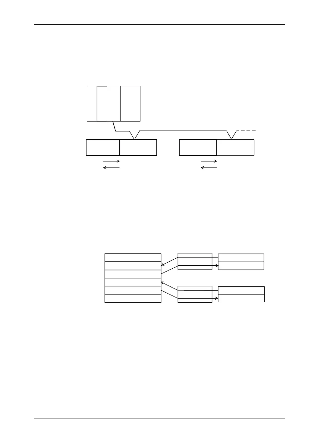
Example 2:
Remote I/O system in which the FP0 Control Unit has one FP0
I/O Link Unit. (I/O Link error flag is valid.)
FP3/FP10SH
Power supply
CPU
Master Unit
I/O
Communication cable
Station No. 1
(first
expan–
sion)
Station No. 2
FP0
Control Unit
FP0
Control Unit
FP0
I/O Link Unit
FP0
I/O Link Unit
WY2,3
WY2,3
WX2,3
WX2,3
WX64,65
WX68,69
WY66,67
WY70,71
(X20~3E)
(X20~3E)
(FP0)
(FP0)
(FP3/FP10SH) (FP3/FP10SH)
(first
expan–
sion)
Station No. 2
The base word number that the Master Unit
at the left can control is 64.
[X3F is an I/O Link error flag]
[X3F is an I/O Link error flag]
The difference from example 1 is that the MSB (most
significant bit) of 2 words input (here X3F) is the I/O Link error
flag. This error flag indicates the communication condition
between this I/O Link Unit and the master unit.
The relationship of Inputs/Outputs between FP3/FP10SH and
FP0 in the above figure is shown below.
FP3/FP10SH I/O map
I/O Link Unit
FP0 I/O map
Input
Input
Input
Input
Output
Output
Output
Output
WX64,65 (X640 to 65F)
WY66,67 (Y660 to 67E)
WX68,69 (X680 to 69F)
WY70,71 (Y700 to 71E)
Station No. 1
(first expansion)
Station No. 2
(first expansion)
WY2,3 (Y20 to 3F)
WX2,3 (X20 to 3E)
WY2,3 (Y20 to 3F)
WX2,3 (X20 to 3E)
X3F is an I/O Link error flag
X3F is an I/O Link error flag
(Y67 and Y71F will be invalid)
As this X3F is allocated as the I/O Link error flag in the FP0 I/O
map, Y67F and Y71F in the FP3/FP10SH I/O map are invalid.
 Loading...


