FP0 Hardware 5.4 Using the FP0 I/O Link Unit
5-11Matsushita Electric Works (Europe) AG
5.4.4 Remote I/O System Communication Error Flag (FP0)
The communication condition of the Remote I/O System can be checked from the FP0
side. This is only valid when operation mode selection switch No.4 is ON.
Communication condition Normal Trouble
I/O link error flag 0 1
Notes
This flag indicates the state of the communication condition
between the FP0 I/O Link Unit and the Master Unit. If a
communication error occurs at other slave stations while the
Master Unit’s operation mode switch No. 7 (communication
error operation mode) is set to ”0” (operation stop mode), this
flag turns on.
This flag is assigned the MSB (most significant bit) of Input 2
words [32bits: WX (n, n+1)] in the FP0 I/O Link Unit. For
details, see page 5-11, Example 1.
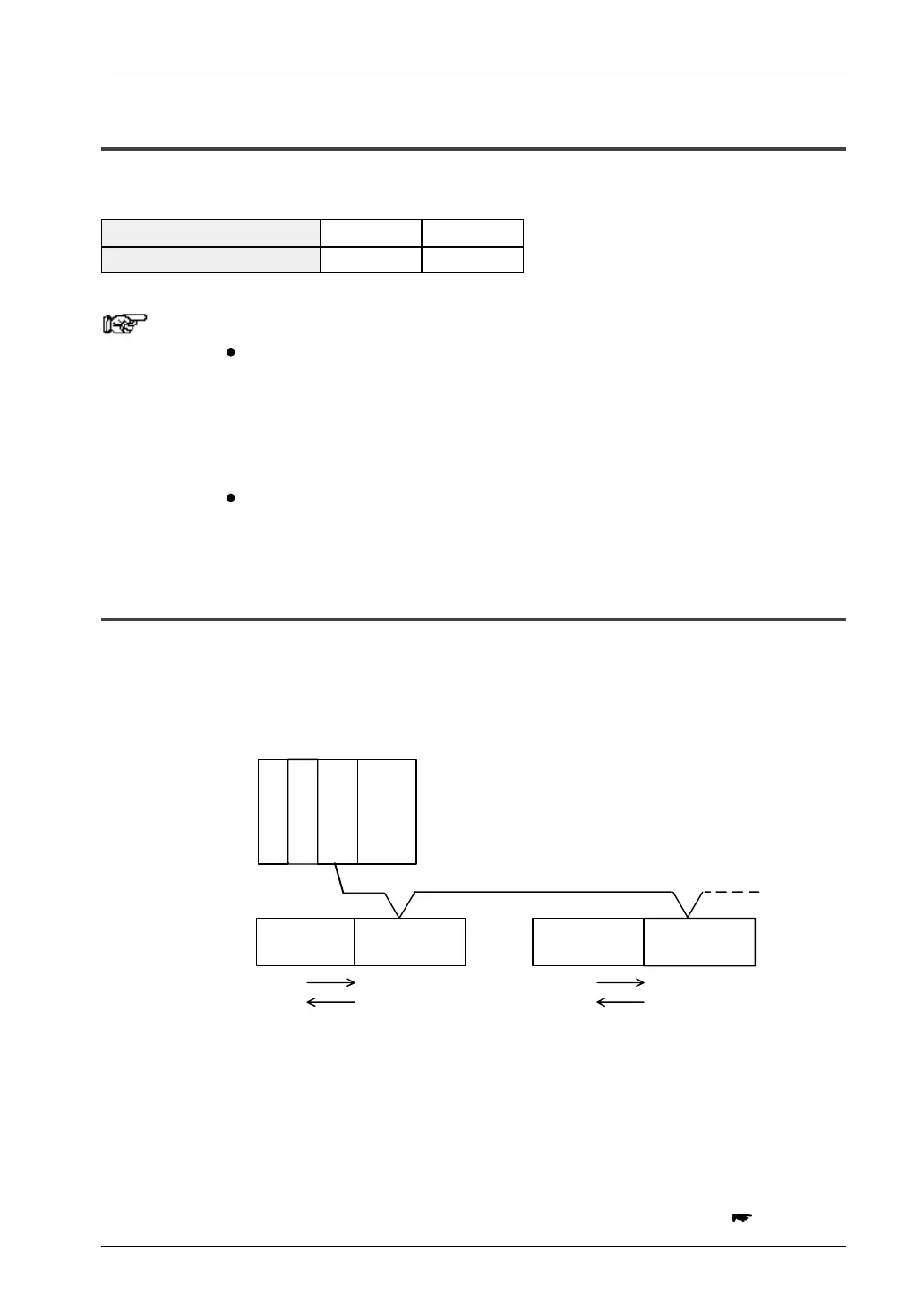
5.4.5 I/O Number
Example 1:
Below is an example of the Remote I/O System connected to
the FP0 I/O Link Unit. (I/O link error flag is invalid.)
FP3/FP10SH
Power supply
CPU
Master Unit
I/O
Communication cable
To other slave stations
Station No. 1
(first
expan–
sion)
Station No. 2
FP0
Control Unit
FP0
Control Unit
FP0
I/O Link Unit
FP0
I/O Link Unit
WY2,3
WY2,3
WX2,3
WX2,3
WX64,65
WX68,69
WY66,67
WY70,71
(X20~3F)
(X20~3F)
(FP0)
(FP0)
(FP3/FP10SH) (FP3/FP10SH)
(first
expan–
sion)
The base word number that the Master Unit
at the left can control is 64.
The I/O Link Unit is identified by the Master Unit in the
FP3/FP10SH as a slave station. The total number of I/O points
is 64 (32X, 32Y, i.e input: 32 points, output: 32 points).
next page

 Loading...

