FP0 Hardware 2.3 Internal Circuit Diagram
2-15Matsushita Electric Works (Europe) AG
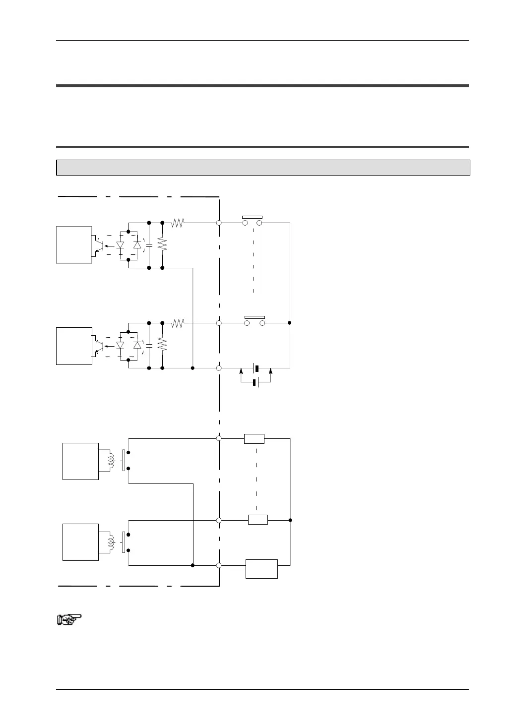
2.3 Internal Circuit Diagram
2.3.1 Relay Output Type
FP0-C10RS/C10CRS/C14RS/C14CRS
Internal
circuit
X0
Xn
COM
Y0
Yn
COM
Power
supply
Input side
Output side
5.6kΩ
(see note 1)
5.6kΩ
Internal
circuit
Internal
circuit
Internal
circuit
Load
Load
(see note 1)
24V DC (see note 2)
Notes
1) The resistor in the control unit is 2kW for X0 through X5, and
1kW for X6 and X7.
2) Either positive or negative polarity is possible for the input
voltage supply.

 Loading...

