FP0 HardwareSelf-Diagnostic and Troubleshooting
11-2
Matsushita Electric Works (Europe) AG
11.1 Self-Diagnostic Function
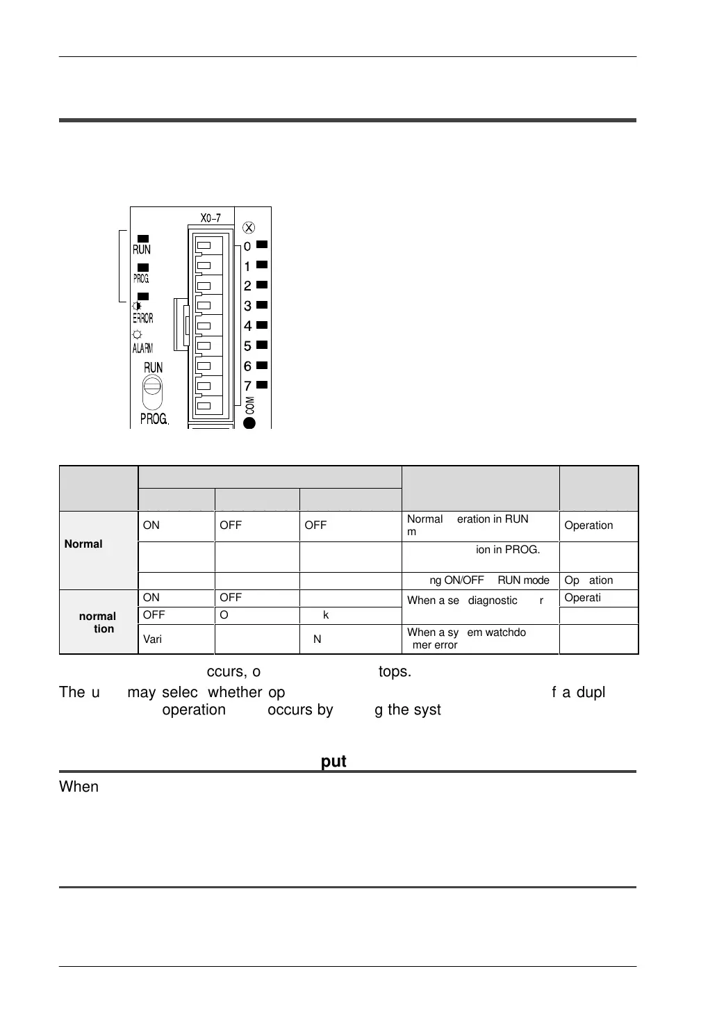
The FP0 control unit has a self-diagnostic function which identifies errors and stops
operation if necessary. When an error occurs, the status of the status indicator LEDs
on the FP0 control unit change, as shown in the table.
Status
indicator
LEDs
LED status
Program
Condition
RUN PROG. ERROR/ALARM
Description
execution
status
ÁÁÁ
ON
ÁÁÁ
OFF
ÁÁÁ
OFF
Normal operation in RUN
mode
ÁÁ
Operation
Normal
condition
OFF
ON
OFF
Normal operation in PROG.
mode
Stop
Blink
OFF
OFF Forcing ON/OFF in RUN mode
Operation
ON
OFF
Blink
When a self-diagnostic error
Operation
Abnormal
OFF
ON
Blink
When a self-diagnostic error
occurs
Stop
Abnormal
condition
Varies
Varies
ON
When a system watchdog
timer error occurs
Stop
Normally, if an error occurs, operation of FP0 stops.
The user may select whether operation is to be continued or stopped if a duplicate
output error or operation error occurs by setting the system registers.
11.1.1 Allowing Duplicated Output
When you change system register 20 settings (“ENAB”) using the programming
software, duplicated output is not regarded as an error and the FP0 continues to
operate.
11.1.2 Continuing After an Operation Error
When you change system register 26 settings (“CONT”) using the programming
software, the FP0 continues to operate. In this case, even if the FP0 continues to
operate, this is regarded as an error.

 Loading...

