FP0 Hardware 2.4 Pin Layouts
2-21Matsushita Electric Works (Europe) AG
2) The two COM terminals of input terminal (X0–7) are connected
internally, however they should be externally connected as
well.
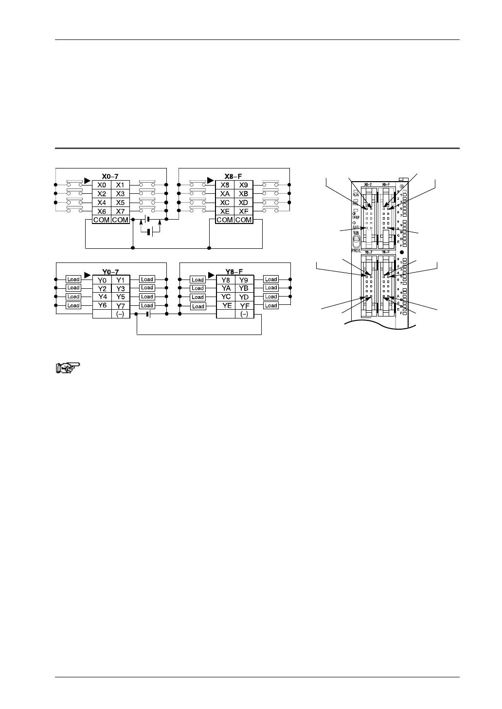
2.4.5 C32T/C32CT
(+)
X8
Y8 Y9
X9X0 X1
Y1
COM
COM
(–)(+) (+) (–)
Inputs Inputs
Outputs Outputs
Y0
(+)
(see note 1)
Notes
1) Either positive or negative polarity is possible for the input
voltage supply.
2) The four COM terminals of input terminals (X0–7 and X8–F) are
connected internally, however they should be externally
connected as well.
3) The (+) terminals of output terminals (Y0–7) and output
terminals (Y8–F) are connected internally, however they
should be externally connected as well.
4) The (–) terminals of output terminals (Y0–7) and output
terminals (Y8–F) are connected internally, however they
should be externally connected as well.

 Loading...

