FP0 Hardware 5.4 Using the FP0 I/O Link Unit
5-9Matsushita Electric Works (Europe) AG
5.4 Using the FP0 I/O Link Unit
In this section, the operation mode, master unit and slave connections, the remote I/O
system communication error flag and I/O numbers are explained.
5.4.1 Operation Mode
The operation mode is set with the operating mode selection switch.
Terminal Station Selection
The terminal station is located at each end of the communication line. If it is not set up
properly, a communication error may occur. (For more details, see ACGM0028END,
REMOTE I/O SYSTEM.)
Communication Error Output Mode
If the communication error occurs in the Remote I/O System, the FP0 I/O Link Unit will
select either the “Output OFF” or “Output HOLD” mode. (In the case below, the output
of the FP0 I/O Link Unit is the output from the FP3 / FP10SH to the FP0. This is the input
for the FP0.) However, if system register No. 27 in the FP3 / FP10SH CPU is set to ”0”
and a communication error occurs with a slave station, the output mode will be set to
“Output OFF”.
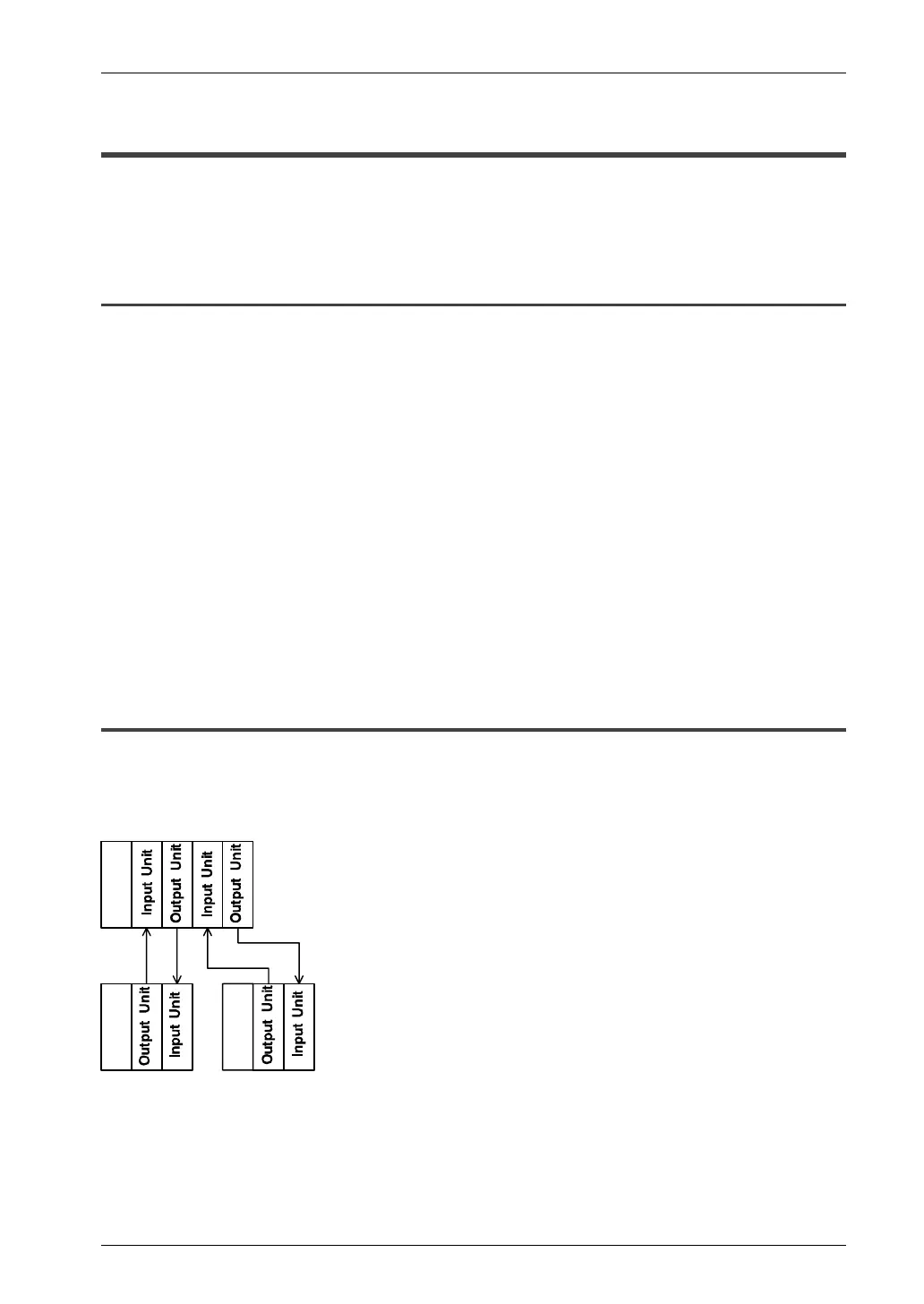
5.4.2 Parallel Versus Serial Connection
In a parallel setup, the input and output of the FP0 are directly connected to the input
and output of the FP3/FP10SH, for example. I/O information can be exchanged
asynchronously between the FP3/FP10SH and the FP0.
FP3/FP10SH
FP0
FP0
Parallel connection
(multi–conductor cable)

 Loading...

