FP0 Hardware 4.5 Wiring
4-13Matsushita Electric Works (Europe) AG
4.5 Wiring
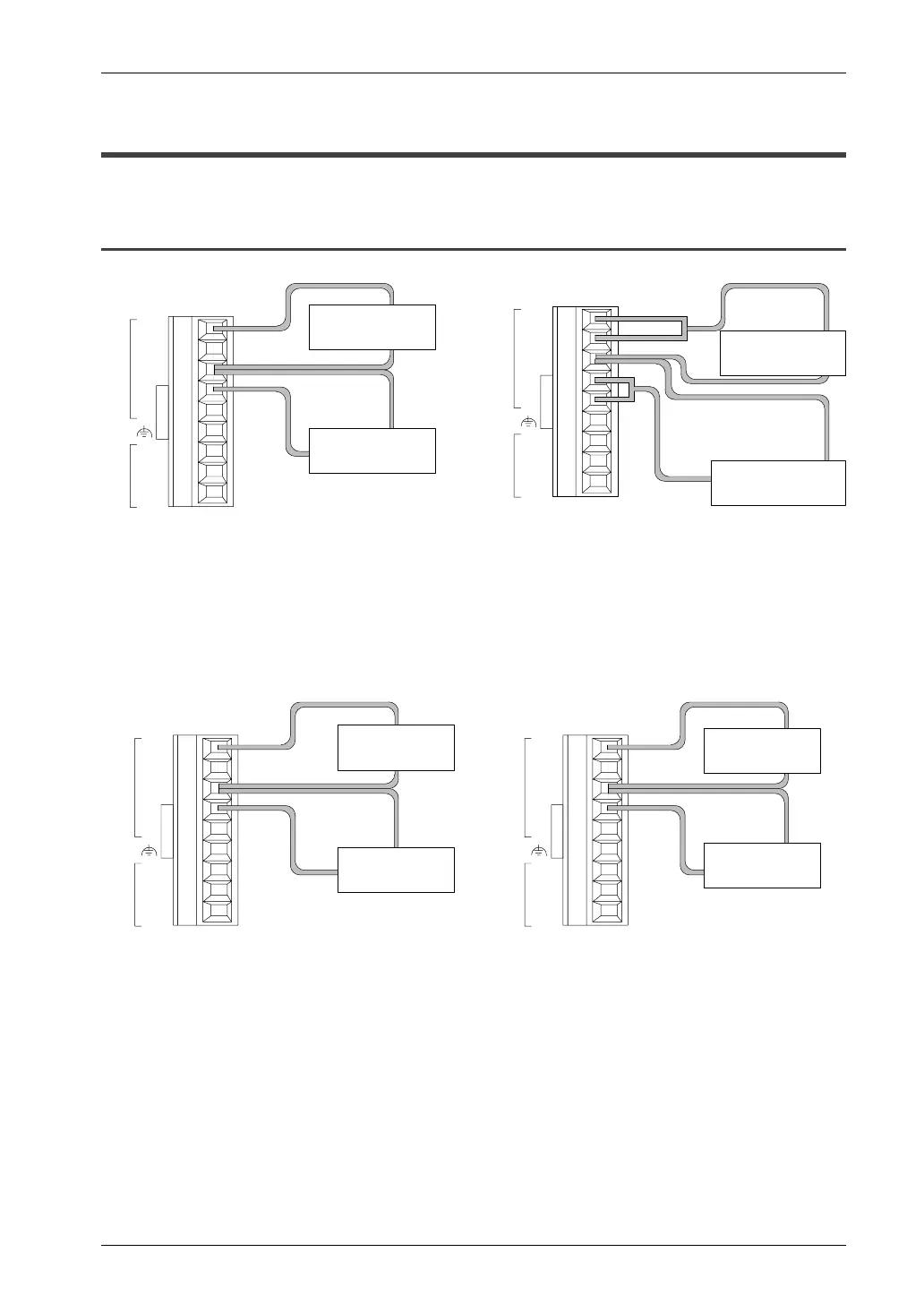
4.5.1 Analog Input Wiring
V 0
I 0
V 1
I 1
COM
V
I
COM
IN
OUT
V 0
I 0
V 1
I 1
COM
V
I
COM
IN
OUT
Voltage input
Connect input instrument between IN/V and
IN/COM terminal.
First, connect both IN/V terminal and IN/I terminal.
And then connect input instrument between it and
IN/COM terminal.
Input instrument
(CH1)
Current input
V 0
I 0
V 1
I 1
COM
V
I
COM
IN
OUT
Thermocouple input
(when measured at temperature higher
than the temperature of the terminal)
Connect IN/V terminal to the (+) side of the
thermocouple, and connect IN/COM terminal to the (–)
side of the thermocouple.
(+)
(–)
(+)
V 0
I 0
V 1
I 1
COM
V
I
COM
IN
OUT
Thermocouple input
(when measured at temperature lower
than the temperature of the terminal)
Connect IN/V terminal to the (–) side of the
thermocouple, and connect IN/COM terminal to the
(+) side of the thermocouple.
(–)
(+)
(–)
Thermocouple
(CH0)
Thermocouple
(CH1)
Input instrument
(CH1)
Input instrument
(CH0)
Thermocouple
(CH0)
Thermocouple
(CH1)
Input instrument
(CH0)
 Loading...


