FP0 Hardware 4.2 Specifications
4-7Matsushita Electric Works (Europe) AG
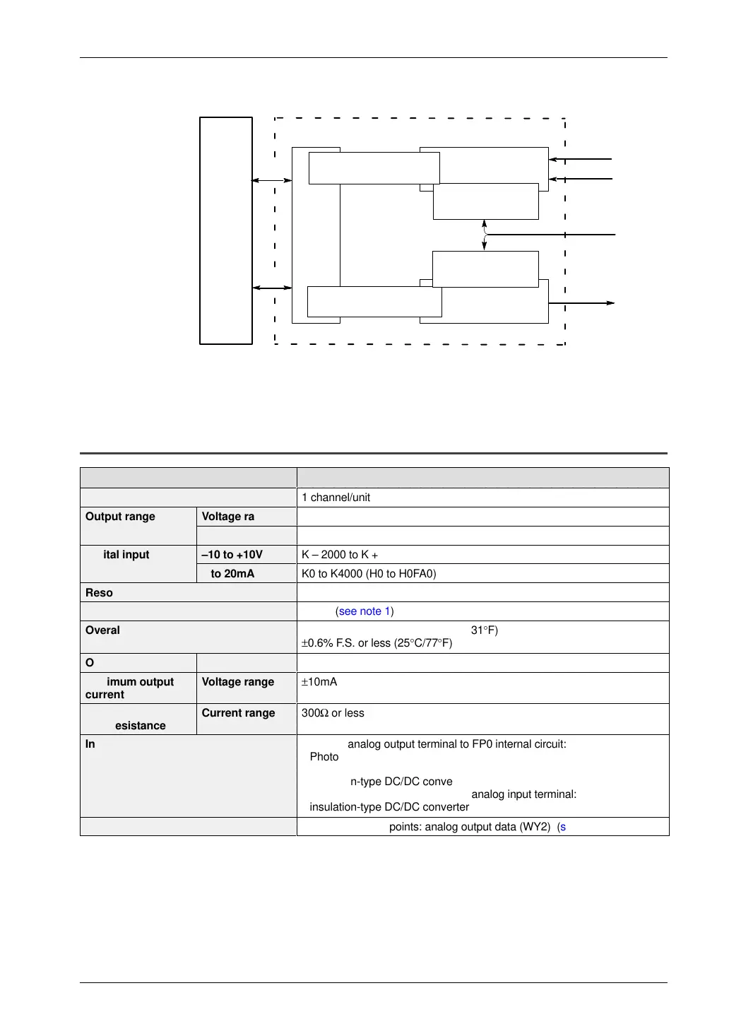
5) Refer to the schematic diagram of insulation methods below.
FP0
Control
unit
I/F
Photocoupler
insulation
Analog input
Analog output
Analog I/O unit
DC/DC converter
insulation
CH0
24V DC
+5V
Bus
CH1
DC/DC converter
insulation
Photocoupler
insulation
6) The number for the input contact point being used varies
depending on the expansion location (see page 7 - 5).
4.2.3 Analog Output Specifications
Item Description
Number of output points
ÁÁÁÁÁÁÁÁÁÁÁÁÁÁÁÁÁÁ
ÁÁÁÁÁÁÁÁÁÁÁÁÁÁÁÁÁÁ
1 channel/unit
Output range Voltage range
ÁÁÁÁÁÁÁÁÁÁÁÁÁÁÁÁÁÁ
ÁÁÁÁÁÁÁÁÁÁÁÁÁÁÁÁÁÁ
–10 to +10V
Current range
ÁÁÁÁÁÁÁÁÁÁÁÁÁÁÁÁÁÁ
ÁÁÁÁÁÁÁÁÁÁÁÁÁÁÁÁÁÁ
0 to 20mA
Digital input –10 to +10V
K – 2000 to K + 2000 (HF830 to H07D0)
0 to 20mA
ÁÁÁÁÁÁÁÁÁÁÁÁÁÁÁÁÁÁ
ÁÁÁÁÁÁÁÁÁÁÁÁÁÁÁÁÁÁ
K0 to K4000 (H0 to H0FA0)
Resolution
ÁÁÁÁÁÁÁÁÁÁÁÁÁÁÁÁÁÁ
ÁÁÁÁÁÁÁÁÁÁÁÁÁÁÁÁÁÁ
1/4000
Conversion speed
ÁÁÁÁÁÁÁÁÁÁÁÁÁÁÁÁÁÁ
ÁÁÁÁÁÁÁÁÁÁÁÁÁÁÁÁÁÁ
500µs (see note 1)
Overall precision
ÁÁÁÁÁÁÁÁÁÁÁÁÁÁÁÁ
±1% F.S. or less (0 to 55°C/32 to 131°F)
±0.6% F.S. or less (25°C/77°F)
Output impedence Voltage range
0.5Ω
Maximum output
current
Voltage range
ÁÁÁÁÁÁÁÁÁÁÁÁÁÁÁÁ
±10mA
Allowable output
load resistance
Current range
ÁÁÁÁÁÁÁÁÁÁÁÁÁÁÁÁÁÁ
ÁÁÁÁÁÁÁÁÁÁÁÁÁÁÁÁÁÁ
300Ω or less
Insulation method (see note 2)
ÁÁÁÁÁÁÁÁÁÁÁÁÁÁÁÁ
ÁÁÁÁÁÁÁÁÁÁÁÁÁÁÁÁ
ÁÁÁÁÁÁÁÁÁÁÁÁÁÁÁÁ
Between analog output terminal to FP0 internal circuit:
Photocoupler insulation
Between analog output terminal to analog I/O unit external power supply:
insulation-type DC/DC converter
Between analog output terminal to analog input terminal:
insulation-type DC/DC converter
Number of output contact points
ÁÁÁÁÁÁÁÁÁÁÁÁÁÁÁÁÁÁ
ÁÁÁÁÁÁÁÁÁÁÁÁÁÁÁÁÁÁ
16 output contact points: analog output data (WY2) (see note 3)

 Loading...

