0
5
0
5
STATION
No.
upper
lower
MODE
1
2
3
4
OFF ON
FP0 Hardware 5.1 FP0 I/O Link Unit (MEWNET–F)
5-3Matsushita Electric Works (Europe) AG
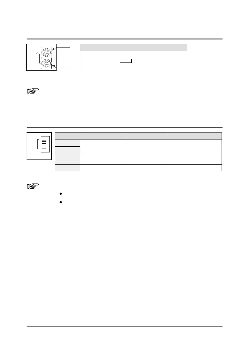
5.1.2 Station Number Selection Switches
Functional description
– Sets the station number of the FP0 I/O Link Unit.
– The working range is 01–32 .
– If the switches are not within this range, a selection error will
occur and communication will be impossible.
Note
In case of a selection error, the ALARM LED will flash.
5.1.3 Operation Mode Selection Switches
Switch No. Function OFF ON
1
2
Terminal station selection. Not a terminal station. Operates as a terminal station.
3 Output condition during a
communication error.
Not retained. Retained.
4 I/O Link error flag. Invalid. Valid.
Notes
Switches 1 and 2 must always be set the same (ON or OFF).
In case I/O Link error flag is valid, the MSB (most significant
bit) of the 2 words allocated [32 bit: WX (n, n+1)] is assigned
as an error flag to the Control Unit (0: normal, 1: abnormal).

 Loading...

