FP0 HardwareFP0 I/O Link Unit (MEWNET–F)
5-8
Matsushita Electric Works (Europe) AG
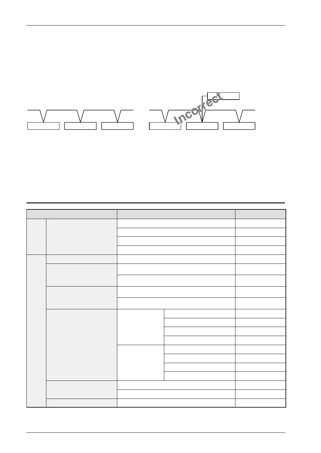
When connecting the communication cable, be sure to connect the side terminal of
a slave station to the side terminal of the FP0 I/O Link Unit, and the side terminal
of a slave station to the side terminal of the FP0 I/O Link Unit. No more than two pairs
of cables should be connected to one RS485 port.
slave station slave station
slave station slave station slave station slave station
Correct
slave station
Be sure to follow the wiring diagram and the terminal symbol sheet when setting up your
system.
Tightening torque for both terminals and fixing screws must be 0.5 to 0.6 Nm (5.1 to 6.1
kgfcm).
5.3.7 Related Product Names and Numbers
Product name Specifications Order number
r
Master Unit FP–2 Multi–Wire Link Unit FP2–MW
ster
tion
FP3 Remote I/O Master Unit AFP3742
Ma
sta
FP–C CPU with MEWNET–F Board AFC3224
FP–C MEWNET–F Master Board AFC3740
Slave Unit FP3 Remote I/O Slave Unit AFP3743
FP I/O Terminal Board Operating voltage: 12V DC, 0.2A Tr. Output AFP87445
Connector type
Operating voltage: 24V DC, 0.2A Tr. Output AFP87446
FP I/O Terminal board Operating voltage: 24V DC, 0.2A Tr. Output AFP87444
Screw terminal board type
Operating voltage: 24V DC, 2A Ry. Output AFP87432
FP I/O Terminal Unit Basic Unit 8–point input unit AFP87421
tion
16–point input unit AFP87422
stat
DC Input
8–point output unit AFP87423
lave
0.5A Tr. Output
16–point output unit AFP87424
Sl
Expansion Unit 8–point input unit AFP87425
16–point input unit AFP87426
DC Input
8–point output unit AFP87427
0.5A Tr. Output
16–point output unit AFP87428
FP1 I/O Link Unit Operating voltage: 24V DC AFP1732
Operating voltage: 100 to 240V AC AFP1736
FP–M I/O Link Board Operating voltage: 24V DC AFC1732

 Loading...

