FP0 Hardware 4.1 Parts and Terminology
4-3Matsushita Electric Works (Europe) AG
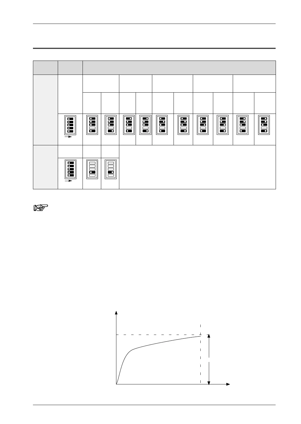
4.1.1 Analog Mode Switch Setting
Mode Switch
number
Range
Analog
input
range
0 to 5V
0 to 20mA
–10 to +10V
K type thermo–
couple (see notes
3, 4)
J type thermo–
couple (see notes
3, 4)
T type thermo–
couple (see notes
3, 4)
switching
1 to 3, 5
No
averaging
(see
note 1)
With
averaging
(see
note 2)
No aver–
aging
(see
note 1)
With av–
eraging
(see
note 2)
Temper–
ature of
terminal
to
1000°C
–100°C
to
temper–
ature of
terminal
Temper–
ature of
terminal
to 750°C
–100°C
to
temper–
ature of
terminal
Temper–
ature of
terminal
to 350°C
–100°C
to
temper–
ature of
terminal
1
2
3
ON
5
Analog
output
4
0 to
20mA
–10 to
+10V
range
switching
ON
4
Notes
1) No averaging: Conversion data is set for the specified input
contact point area for each A/D conversion, on each channel.
2) With averaging: On each channel, for each A/D conversion,
the maximum and minimum values from the data of the last
ten times are excluded, and the data from the other eight times
is averaged, and the result set (see page 4-17).
3) If a thermocouple setting is used, averaging is carried out,
regardless of the switch settings (see page 4-18).
4) After turning on the analog unit, 20 minutes are required for
the transient state to reach a measurement accuracy of 99%.
During this time, deviations of 10C can occur.
time
measurement
accuracy
20 min.
99%
10C

 Loading...

