FP0 Hardware C.1 Special Data Registers
C-5Matsushita Electric Works (Europe) AG
Addresses Description
T32CP Other Types
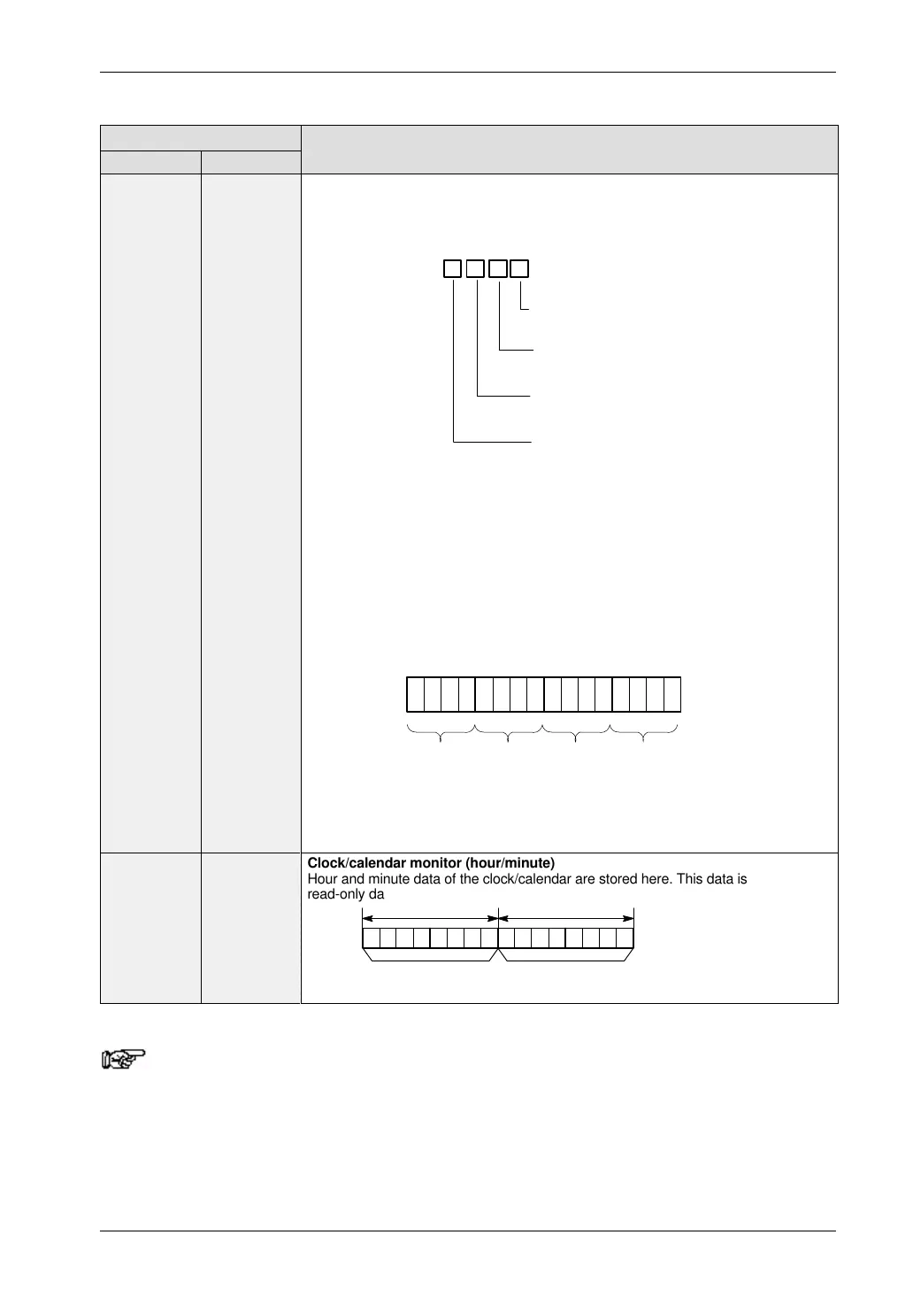
DT90052 DT9052 High-speed counter control flag
A value can be written with an MV (F0) instruction to reset the high-speed counter,
disable counting, stop high-speed counter instruction (F168), and clear the high-
speed counter.
Control code setting
Software is not reset: H0 (0000)
Perform software reset: H1 (0001)
Disable count: H2 (0010)
Disable hardware reset: H4 (0100)
Stop pulse output (clear instruction): H8 (1000)
Perform software reset and stop pulse output: H9 (1001)
The 16 bits of DT9052 are allocated in groups of four to high-speed channels 0 to 3
as shown below.
Control code = (Binary)
Software reset
0: Yes / 1: No
Count
0: Enable / 1: Disable
Hardware reset
0: Enable / 1: Disable
High–speed counter clear
0: Continue / 1: Clear
bit 15 0
for ch3
34781112
for ch2 for ch1 for ch0
DT9052
A hardware reset disable is only effective when using the reset inputs (X2 and X5). In
all other cases it is ignored.
When using pulse output, a hardware reset input is equivalent to an home point proxi-
mate input.
DT90053
(see note)
ÑÑÑÑÑÑÑÑÑÑÑÑÑÑÑÑÑÑ
ÑÑÑÑÑÑÑÑÑÑÑÑÑÑÑÑÑÑ
ÑÑÑÑÑÑÑÑÑÑÑÑÑÑÑÑÑÑ
ÑÑÑÑÑÑÑÑÑÑÑÑÑÑÑÑÑÑ
Clock/calendar monitor (hour/minute)
Hour and minute data of the clock/calendar are stored here. This data is
read-only data; it cannot be overwritten.
Higher 8 bits Lower 8 bits
Hour data
H00 to H23 (BCD)
Minute data
H00 to H59 (BCD)
Note
An expansion memory unit is necessary.

 Loading...

