FP0 Hardware 3.3 Internal Circuit Diagram
3-13Matsushita Electric Works (Europe) AG
Note
The output number given above is the output number when the
expansion output unit is installed as the first expansion unit
(see page 7 - 4).
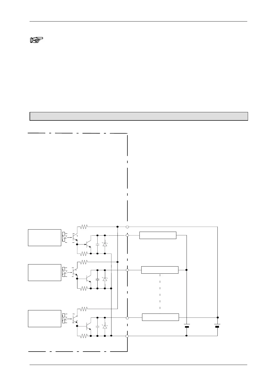
When the load voltage differs from the 24V DC external power supply for driving
the internal circuit
Other than 24V DC load voltage, 5V DC and 12V DC and other load voltages can be
connected.
FP0-E8YT/E16YT
Y20
(+)
Y21
(–)
Y2n
24V DC
(External
power supply
for driving
internal circuit)
5V DC
(Rated load
voltage)
Internal circuit
Load (for 24V DC)
Load (for 5V )
Load (for 5V )
Output side
Internal circuit
Internal circuit

 Loading...

