– 394 – NWA-008853-001 Rev.3.0
97ch4001.fm
NOTE 1: Set the groove on the switch to the desired position.
NOTE 2: When the power is on, flip the MB switch to ON (UP position) before plugging/unplugging the
circuit card.
NOTE 3: Set SW0-1 and SW0-2 as follows:
NOTE 4: When the PBX is a clock source office, set the SW0-1 and SW0-2 on all the DTI cards mounted
in PIM0 to “OFF”.
NOTE 5: Mount the DTI card which receives a source clock signal into PIM0.
NOTE 6: This card must be reset after the SW0-3 to SW0-7 switch settings. Set the MB switch to UP and
then DOWN.
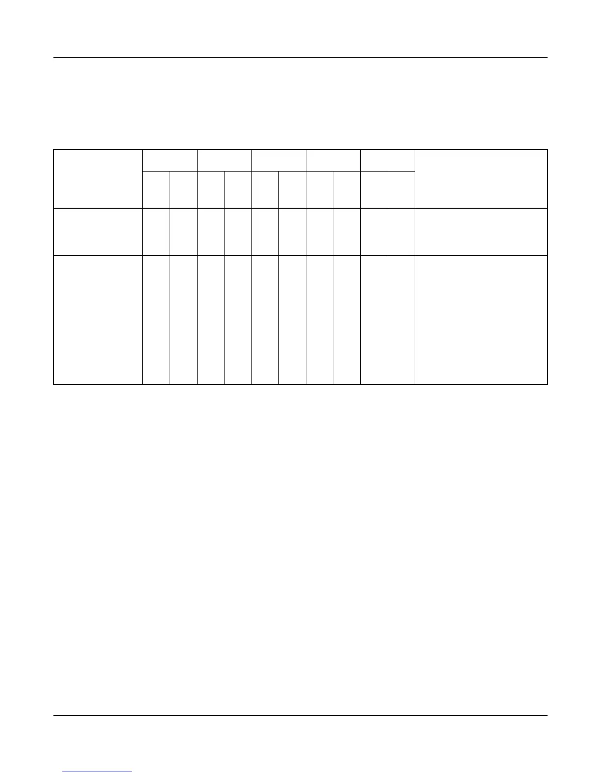
CONDITIONS
DTI0 DTI1 DTI2
· · · · ·
DTI7
REMARKS
SW
0-1
SW
0-2
SW
0-1
SW
0-2
SW
0-1
SW
0-2
SW
0-1
SW
0-2
When one DTI is
provided.
ONOFF–––– ––
MP card will receive the
clock signal from DTI0 at
its PLO0 input.
When more than
one DTI is pro-
vided.
ON OFF OFF ON OFF OFF OFF OFF
MP card will receive the
clock signal from DTI0 at
its PLO0 input, under nor-
mal conditions.
Should a clock failure occur
with DTI0, MP card will
automatically switch to the
PLO1 input which gets
clock from DTI1.
JULY/01/2006
PN-24DTA-C (DTI)