– 403 – NWA-008853-001 Rev.3.0
97ch4001.fm
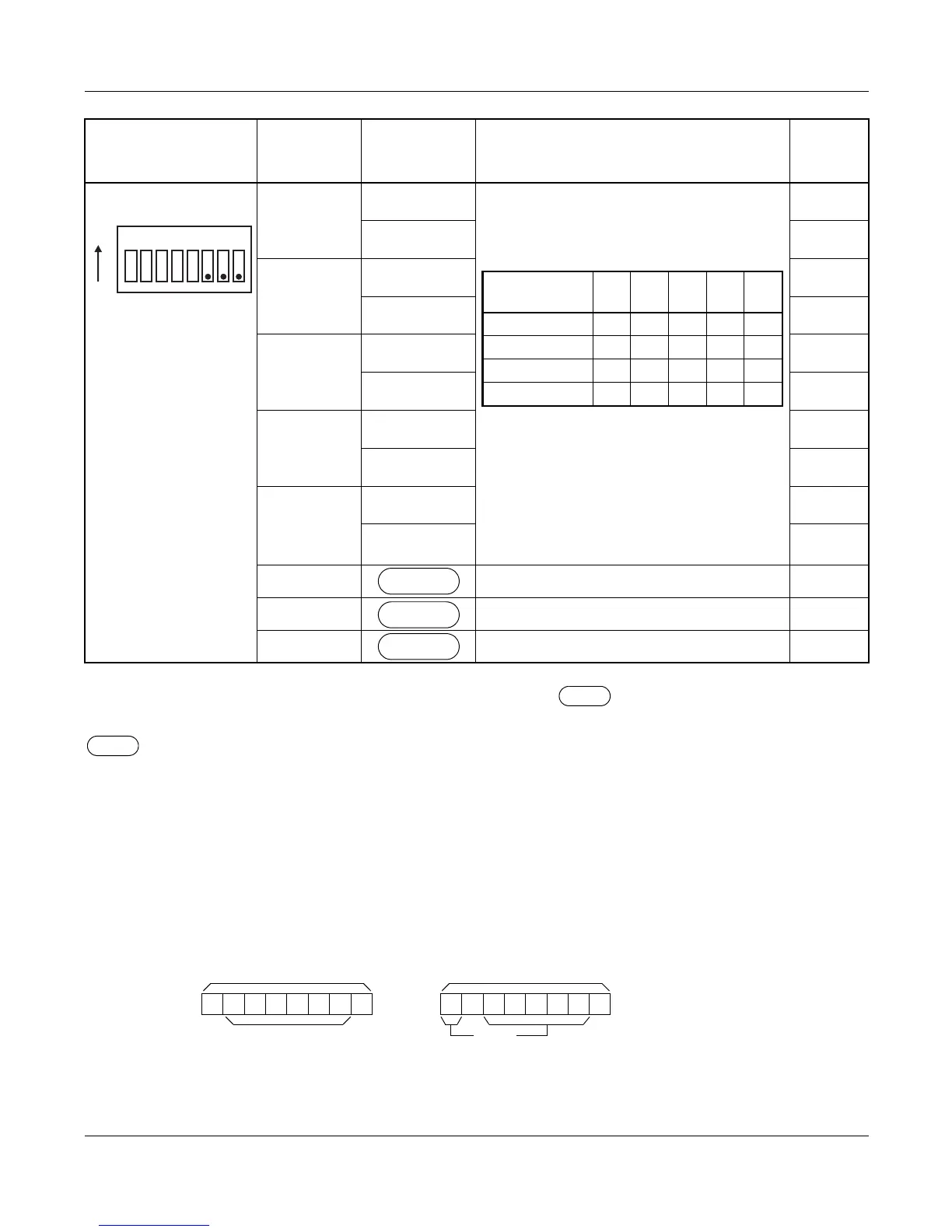
The figure in the SWITCH NAME column and the position of in the SETTING POSITION col-
umn indicate the standard setting of the switch. When the switch is not set as shown by the figure and
, the setting of the switch varies with the system concerned.
NOTE 1: Set the groove on the switch to the desired position.
NOTE 2: When the power is on, flip the MB switch to ON (UP position) before plugging/unplugging the
circuit card.
NOTE 3: This setting is available when SW0-2 is set to ON (Analog Interface).
NOTE 4: The following two kinds of rate adaptation method are available in 48 Kbps data transmission.
The rate adaptation method must be set to match the rate adaptation of clock source office.
SW1 (Dip SW)
1
ON
• Common channel signaling data
transmission speed (For Digital Inter-
face)
• Common channel signaling data
transmission speed (For Analog Inter-
face)
Set switches (SW1-1 - SW1-5) to
OFF.
OFF
2
ON
OFF
3
ON
OFF
4
ON
OFF
5
ON
OFF
6 Not used
7 Always set to OFF
8 Always set to OFF
SWITCH NAME
SWITCH
NUMBER
SETTING
POSITION
FUNCTION CHECK
1
2
3
4
5
6
7
8
ON
TRANSMISSION
SPEED
SW
1-1
SW
1-2
SW
1-3
SW
1-4
SW
1-5
48 Kbps NOTE 4 ON ON OFF OFF ON
48 Kbps NOTE 4 ON ON ON OFF ON
56 Kbps ON ON OFF ON ON
64 Kbps ON ON ON ON ON
OFF
OFF
OFF
1 1
48 Kbps
Data
• SW1-3: OFF
1 1
48 Kbps
• SW1-3: ON
Data
PN-SC00 (CCH)