19
Connection
Digitax SF Instruction Manual
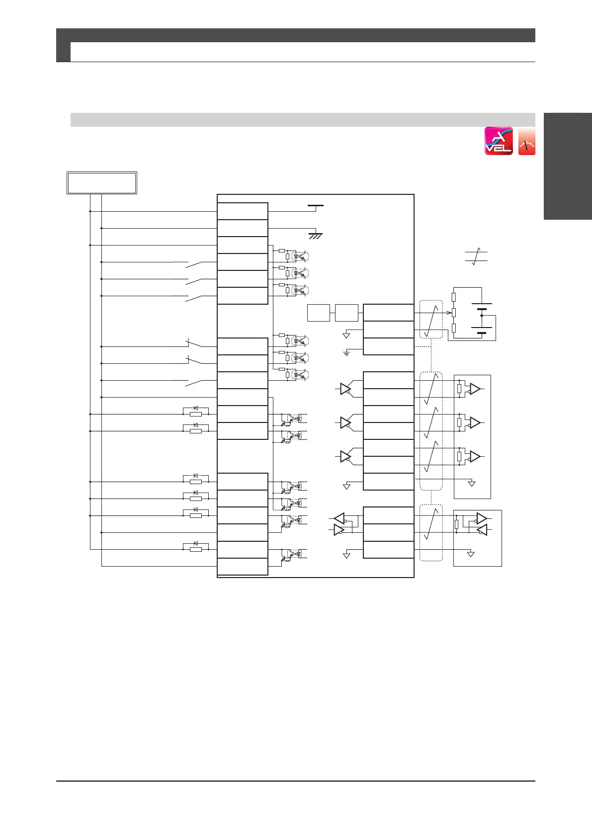
3. Velocity Control Mode
4. Connections
3. Velocity Control Mode
1: 24 V
24 V GND
24 V
G24 V
2: G24 V
3: COM+
4: SVON
5: RESET
6: HOLD
9: CCWL
10: CWL
11: TLSEL1
12: COM
-
13: MBRK
14: SERVO
17: T-LIMIT
18: OCZ
19: SRDY+
20: SRDY
-
21: ALM+
22: ALM
-
FG
36: OUT_A
37: /OUT_A
38: OUT_B
39: /OUT_B
40: OUT_Z
41: /OUT_Z
43: 485
44: /485
45: SG
42: SG
32: A_SPEED
33: A_GND
SG
Control power supply 24 V input
Control power supply GND
I/O power supply 24 V input
INPUT䚷Servo ON
INPUT䚷Alarm reset
INPUT䚷Command input
inhibition
INPUT䚷CCW run limit switch
input
INPUT䚷CW run limit switch
I/O power supply GND
OUTPUT䚷Motor Brake
release
OUTPUT䚷Servo state
OUTPUT Under torque
limit
㻻㼁㼀㻼㼁㼀䚷㻱㼚㼏㼛㼐㼑㼞㻌㼆㻙㼜㼔㼍㼟㼑
䠄open-collector䠅
OUTPUT䚷Servo-Ready+
OUTPUT
䚷
Servo-Ready
-
OUTPUT䚷Alarm State+
OUTPUT
䚷
Alarm State
-
Analog Velocity Command Input
A-phase
output
B-phase
output
Z-phase
output
RS-422 output
Twisted Pair Cable
Frame
Encoder Signal Output
Control Power
Shielded
㻖3
㻖1
㻖1
㻖1
㻖1
㻖2
㻖6
㻖4
㻖5ġġġġġġġġġġ
Servo Drive
4.7 k
Ω
MAX 50 mA
MAX 50 mA
MAX 50 mA
MAX 50 mA
MAX 50 mA
MAX 50 mA
SG
SG
㻖7
VR
+12 V
-
12 V
R
R
LPFA/D
A_GND
RS-485
Host Controller
SG
㻖㻡
㻖㻠
*1) Control power (24V, G24V) and power for I/O (COM+, COM-) must share one common power supply.
*2) When driving a load containing inductance (component such as a relay) connect a protection circuit (diode).
The motor brake cannot be driven directly. Be sure to use a circuit that interfaces with a diode built-in type relay.
Page 46 Connection to general-purpose output signals
*3) The output circuit conguration is an open collector Darlington transistor output. Connects to relays and optical isolators.
Note that when the transistor is on, connector-emitter voltage VCE (SAT) is approximately 1V;
a standard TTL IC does not satisfy VIL and cannot be connected
directly.
*4) Be sure to connect a termination resistor of approximately 220 Ω.
*5) Make the connection to the communication IC signal ground of the host controller that the drive encoder output signals
are connecting to. Connecting signal ground SG to control power GND may result in malfunction.
*6) If Z-phase pulse width is too small to be measured accurately by the host controller, decrease pulse division rate by using pulse output
ratio (parameters No.276.0 and No.278,0) or decrease rotational speed to increase the pulse width.
Pulse width [ms] = 2 / rotational speed [rpm] / (division ratio × 2
17
) × 60 × 1,000.
*7) For the command circuit conguration with a variable resistor (VR) and a resistor (R), VR must be 2kΩ (1/4W or more) and R must be
100Ω to 200Ω (1/4W or more) , so that command input voltage range is -10V to +10V. If the analog velocity command circuit of the
host controller is isolated from 24V control power supply, connect A_GND to signal ground of the host controller, not to GND of control
power, If the analog velocity command circuit is not isolated,
connect A_GND to GND of control power.
Analog Velocity Command
CN1 Connector Wiring Example
ol
input
INPUT Torque limit
selection

 Loading...
