6
PLS
t3 t3 t3 t3
t1 t2 t1 t2
CCW
CW
t5 t5
t5 t5
t6
t4t4 t4t4
A
B
t4t4 t4t4
Digitax SF Instruction Manual
6. Operation
2. Position Control Mode
2. Position Control Mode
1. Pulse Train Command
Required Parameters
Parameter
No.
Name Setting
2.0 Control Mode 0: Position Control Mode (Default)
3.0 Command Mode 1: Pulse Train Command Mode (Default)
32.0 Input pulse form
(*)
Select one.
0: Pulse and direction (PLS & DIR) (Default)
1: Quadrature phase dierence pulse (A-Phase & B-Phase)
2: Input in positive or negative pulse (CCW & CW)
33.0 Input Filter
Helps to reduce possible malfunctions caused by noise.
You must congure this parameter in the case of command input by
open collector.
Default: 4 (150 ns)
5
Settings,
9
Appendices
34.0
Paired Pulse Ratio
(Numerator)
32,768 (Default:1,000 [pulse/rev])
36.0
Paired Pulse Ratio
(Denominator)
Set to [pulse count of the host controller output] divided by 4
Default:1,000 [pulse/rev]
Set the operating mode with the following parameters.
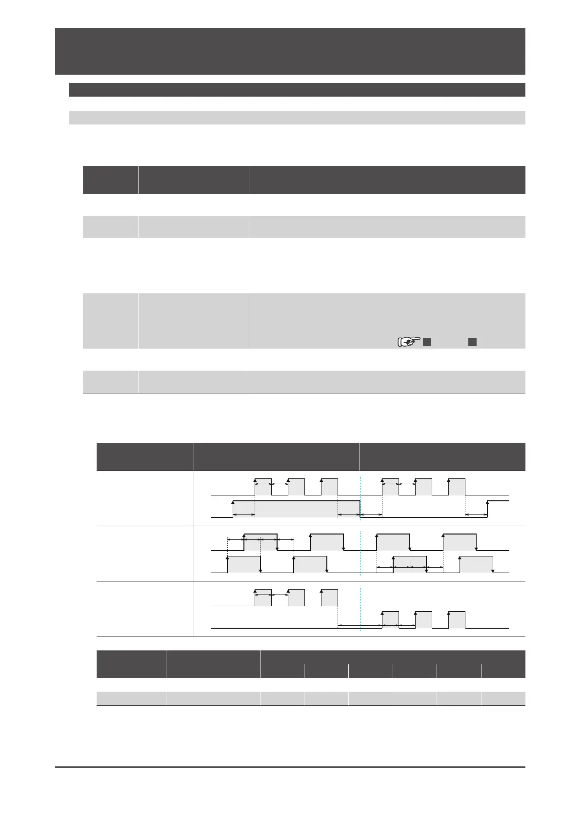
*) Pulse command input form (see the table above) and Minimum Time Interval (see the table below).
Parameters
No32.0
Positive direction command Negative direction command
0
(Default)
Pulse and Direction
(PLS & DIR)
1
Quadrature phase
Dierence pulse
(A-Phase & B-phase)
2
Positive or
Negative pulse
(CCW & CW)
Input pulse
signal
Maximum command
pulse frequency
Minimum time interval [µs]
t1 t2 t3 t4 t5 t6
Differential 4 Mpps 0.125 0.125 2.5 0.25 0.125 0.125
Open collector 200 kpps 2.5 2.5 2.5 2.5 2.5 2.5
The amount of time needed for rising or falling edge of the command pulse input signal must be 0.1 μs or
below. The number of pulses is counted at the rising edge (from low level to high level).
The input logic can be changed with Parameter No.32.3.
A-phase
rises rst.
B-phase
rises rst.

 Loading...
