3
22
ALM−
23
―
49
―
OUTA
36
CMDPLS
26
―
28
CMDDIR
30
―
32
―
34
OUTB
38
OUTZ
40
SG
42
/485
44
―
46
―
48
―
50
/CMDPLS
27 29
―
31
/CMDDIR
33
―
35
―
37
/OUTA
39
/OUTB
41
/OUTZ
43
485
45
SG
47
―
1
24V
3
COM+
5
RESET
7
PCLR
9
CCWL
11
TLSEL1
13
MBRK
15
POSIN
17
T-LIMIT
19
SRDY+
21
ALM+
25
―
2
G24V
4
SVON
6
HOLD
8
―
10
CWL
12
COM−
14
SERVO
16
―
18
OCZ
20
SRDY−
24
―
Connection
Digitax SF Instruction Manual
1. Overview
4. Connections
1. Introduction
The pinout depends on the control mode / motion mode that you are using. Pins are grouped to five categories.
The pinout diagram below illustrates the pin layout when viewing the plug
in connector looking at the pins to which the control cables are soldered
Do not connect anything to reserved pins.
Group Description
General-Purpose Input
The pinout depends on the control mode / motion mode that you are using.
These are input terminals, such as control power, I/O power, and Servo ON.
You can change the input logic. *
General-Purpose Output
The pinout depends on the control mode / motion mode that you are using.
This is an output terminal such as Servo Status that connects to the host controller
You can change the output logic. *
Command Input
The pinout depends on the control mode / motion mode that you are
using. This is an input terminal that receives a command signal from the
host controller such as Pulse Train Command or Analog Command.
Encoder Output
A terminal to output encoder pulse to the host controller.
RS-485 Communication
RS-485 interface to communicate with the host controller.
*
page 24 Descriptions of CN1 Connector signals
page 24
page 45
Descriptions of CN1 Connector Signals
Interface Circuit of CN1 Connector
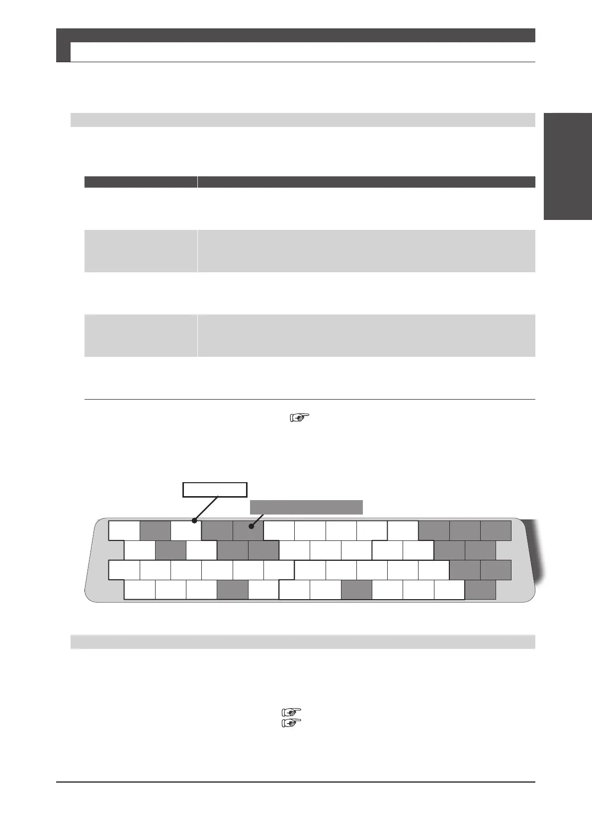
Example: Position control mode- Pulse Train Command, Dierential, Standard I/O Conguration
Pinout Diagram
:Pins are grouped to ve categories.
Boxed area
Painted area marked with (-)
:Reserved pins
CN1 Connector Wiring Example
Example of CN1 Connector Wiring The pinout depends on the control mode・motion mode that you are using.
For actual wiring, check the pin numbers etched on the connector body as well.
For further details, refer to Descriptions of CN1 Connector Signals and Interface Circuit of CN1 Connector.