48
4. Connections
Digitax SF Instruction Manual
5. Descriptions of CN1 Connector Signals
CA
Connection to Analog Command Signal
Control Mode
P S T
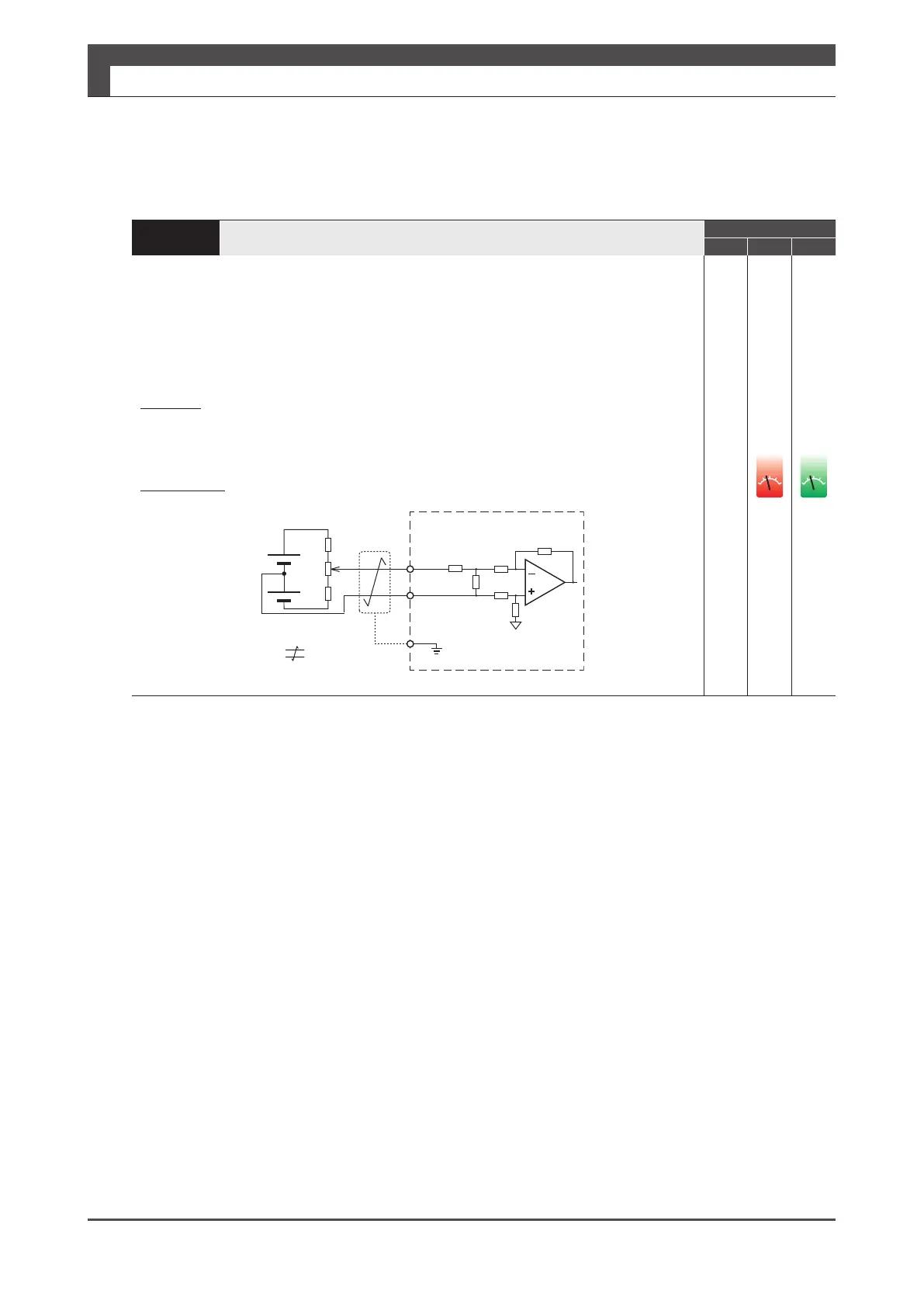
Input voltage tolerance range is ±10 V. For input circuit impedance, see the gure below.
For the command circuit conguration with a variable resistor (VR) and a resistor (R), VR
must be 2kΩ (1/4W or more) and R must be 100 Ω to 200 Ω (1/4W or more), so that
command input voltage range is -10V to +10V.
Be sure to use shielded twisted-pair cables as a noise countermeasure.
■ Isolation/non-isolation of the host analog command circuit and 24V control power
If isolated
Connect A-GND with signal ground of the host controller. (Do not connect to GND of
control power)
If not isolated
Connect A_GND with GND of control power.
32
(ASPEED,ATRQ)
33
(AGND)
ĴŬϮ
ĹįijŬϮ
A_GND
Ĭ
Ƚ
FG
ŗœ
ĬIJijŗ
ȽIJijŗ
œ
œ
Shield
Twisted-paircable
Drive
ol
ol

 Loading...
