18
22
ALM−
23
―
49
―
OUTA
36
―
26
―
28
―
30
ASPEED
32
―
34
OUTB
38
OUTZ
40
SG
42
/485
44
―
46
―
48
―
50
―
27 29
―
31
―
33
AGND
35
―
37
/OUTA
39
/OUTB
41
/OUTZ
43
485
45
SG
47
―
1
24V
3
COM+
5
RESET
7
―
9
CCWL
11
TLSEL1
13
MBRK
15
―
17
T-LIMIT
19
SRDY+
21
ALM+
25
―
2
G24V
4
SVON
6
HOLD
8
―
10
CWL
12
COM−
14
SERVO
16
―
18
OCZ
20
SRDY−
24
―
4. Connections
Digitax SF Instruction Manual
3. Velocity Control Mode
3. Velocity Control Mode
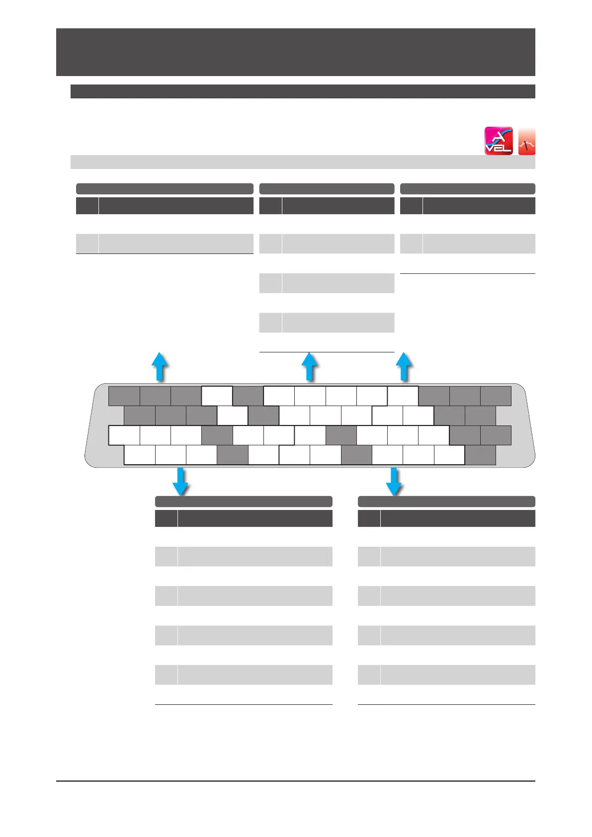
1. Analog Velocity Command
Pin
No.
Signal
Description
32
A_SPEED
Analog Command
33
A_GND
Analog Command Ground
Pin
No.
Signal
Description
1
24V
Control power 24V
2
G24V
Control power GND
3
COM+
I/O Power 24V
4
SVON
Servo ON
5
RESET
Alarm reset
6
HOLD
Command input prohibited
9
CCWL
CCW drive limit switch input
10
CWL
CW drive limit switch input
11
TLSEL1
Torque Limit
Pin
No.
Signal
Description
36
OUT_A
A-phase
37
/OUT_A
/A-phase
38
OUT_B
B-phase
39
/OUT_B
/B-phase
40
OUT_Z
Z-phase
41
/OUT_Z
/Z-phase
42
SG
Signal ground
Pin
No.
Signal
Description
44
/485
/Data
43
485
Data
45
SG
Signal ground
General-Purpose Input General-Purpose Output
Command Input Encoder Output RS-485 Communication
Pin
No.
Signal
Description
12
COM -
I/O power GND
13
MBRK
Motor Brake release
14
SERVO
Servo status
17
T-LIMIT
Torque limiting
18
OCZ
Encoder Z-phase (open collector)
19
SRDY+
Servo ready+
20
SRDY -
Servo ready-
21
ALM+
Alarm status+
22
ALM -
Alarm status-
I/O Connector pinout looking
at the pins to be soldered
Pinout Diagram
ol

 Loading...
