45
Connection
Digitax SF Instruction Manual
5. Descriptions of CN1 Connector Signals
4. Connections
5. Descriptions of CN1 Connector Signals
2. Interface Circuit of CN1 Connector
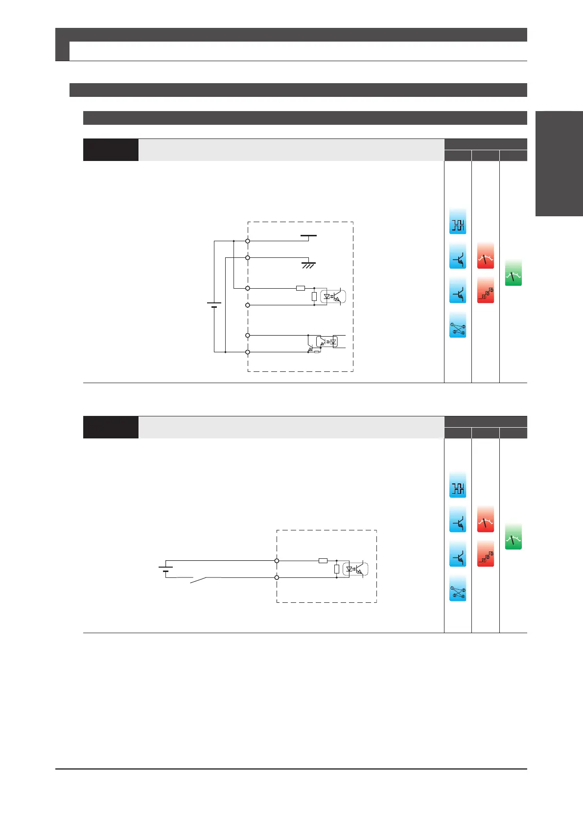
Interface Circuit
PS
Connection to DC24V Power Supply
Control Mode
P S T
Connect control power of the drive and I/O power.
Be careful not to reversely connect plus and minus terminals of the power supply.
Accidental reverse connection may damage the drive.
Control power and I/O power must share one common power supply.
3
(COM+)
General-purposeinput
PinsNo.4-11
(SVONetc.)
Drive
4.7k
Ω
24V
±10%
1
(24V)
2
(G24V)
General-purposeoutput
PinsNo.13-18
(MBRKetc.)
24V
G24V
12
(COM−)
䐟
䐠
䐡
䐢
ol
䐟
䐠
v
ol
PI
Connections to General-Purpose Input Signal
Control Mode
P S T
Pin No.3
Connect to +terminal of I/O power supply. Use power supply of 24V±10%.
Pin No.4 to No.11
Connect to input devices such as switch, open-collector output transistor, and relay contact.
When the input device contact is closed and the contact pair of general-purpose pin and
power supply GND becomes closed, the drive turns on.
I/Opowersupply
4.7k
Ω
Inputdevice
3
(COM+)
General-purposeinput
PinsNo.4-11
(SVONetc.)
łŮűŭŪŧŪŦų
24V
±10%
䐟
䐠
䐡
䐢
ol
䐟
䐠
ol

 Loading...
