14
22
ALM−
23
―
49
―
OUTA
3626 28 30
―
32
―
34
OUTB
38
OUTZ
40
SG
42
/485
44
―
46
―
48
―
50
27 29 31
33
―
35
―
37
/OUTA
39
/OUTB
41
/OUTZ
43
485
45
SG
47
―
1
24V
3
COM+
5
RESET
/PCLR
7
PCSEL1
9
PCSEL3
11
ORG
13
MBRK
15
MEND
17
T-LIMIT
19
SRDY+
21
ALM+
25
―
2
G24V
4
SVON
6
PCSTART1
8
PCSEL2
10
PCSEL4
12
COM−
14
SERVO
16
HEND
18
OCZ
20
SRDY−
24
―
―――
―
――
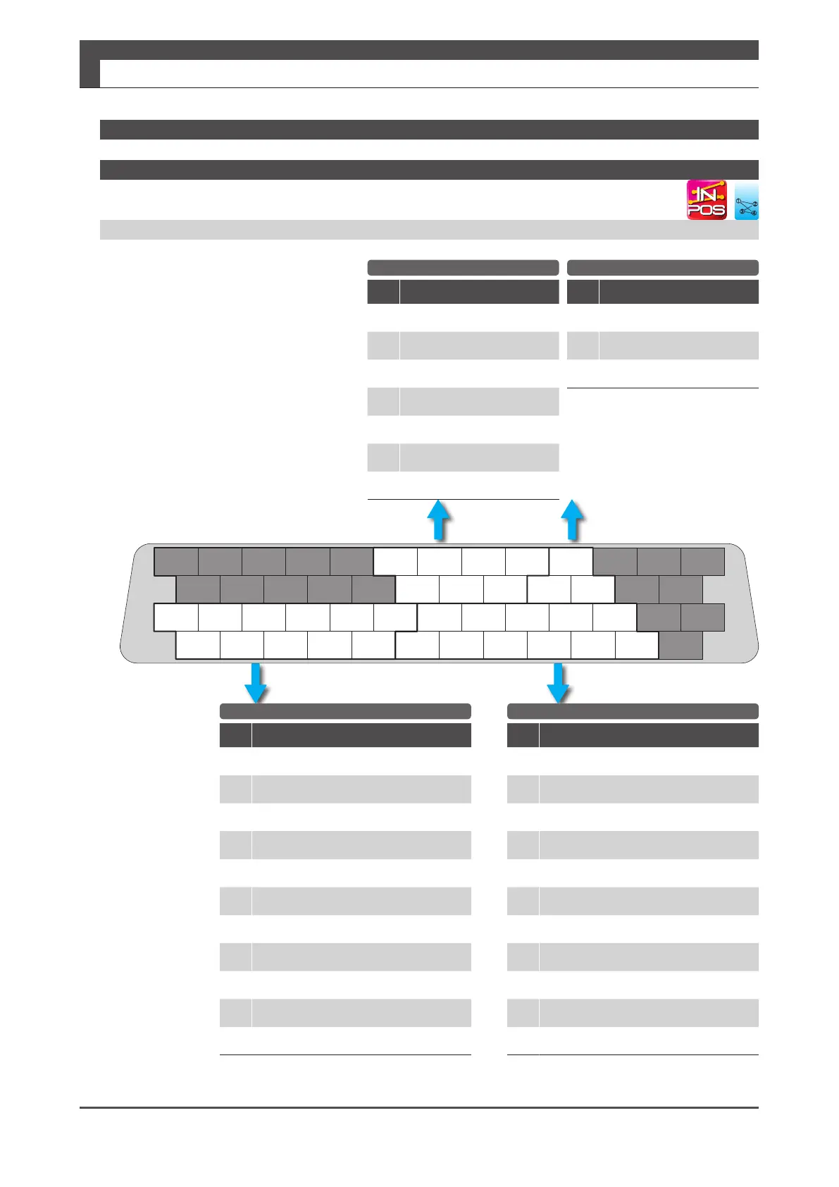
4. Connections
Digitax SF Instruction Manual
2. Position Control Mode
General-Purpose Input General-Purpose Output
Encoder Output RS-485 Communication
2. Internal Position Command
Pin
No.
Signal
Description
1
24V
Control power 24V
2
G24V
Control power GND
3
COM+
I/O Power 24V
4
SVON
Servo ON
5
RESET/PCLR
Alarm Reset / Position Error Counter Clear
6
PCSTART1
Start Forward Rotation
7
PCSEL1
Point No. Select 1
8
PCSEL2
Point No. Select 2
9
PCSEL3
Point No. Select 3
10
PCSEL4
Point No. Select 4
11
ORG
Home position sensor
Pin
No.
Signal
Description
36
OUT_A
A-phase
37
/OUT_A
/A-phase
38
OUT_B
B-phase
39
/OUT_B
/B-phase
40
OUT_Z
Z-phase
41
/OUT_Z
/Z-phase
42
SG
Signal ground
Pin
No.
Signal
Description
44
/485
/Data
43
485
Data
45
SG
Signal ground
Standard I/O Conguration
Pin
No.
Signal
Description
12
COM -
I/O power GND
13
MBRK
Motor Brake release
14
SERVO
Servo status
15
MEND
Motion complete
16
HEND
Homing complete
17
T-LIMIT
Torque limiting
18
OCZ
Encoder Z-phase (open collector)
19
SRDY+
Servo ready+
20
SRDY -
Servo ready-
21
ALM+
Alarm status+
22
ALM -
Alarm status-
I/O Connector pinout looking at
the pins to be soldered
Pinout Diagram
䐟
䐠
䐡
䐢

 Loading...
