49
Connection
Digitax SF Instruction Manual
5. Descriptions of CN1 Connector Signals
4. Connections
5. Descriptions of CN1 Connector Signals
EO
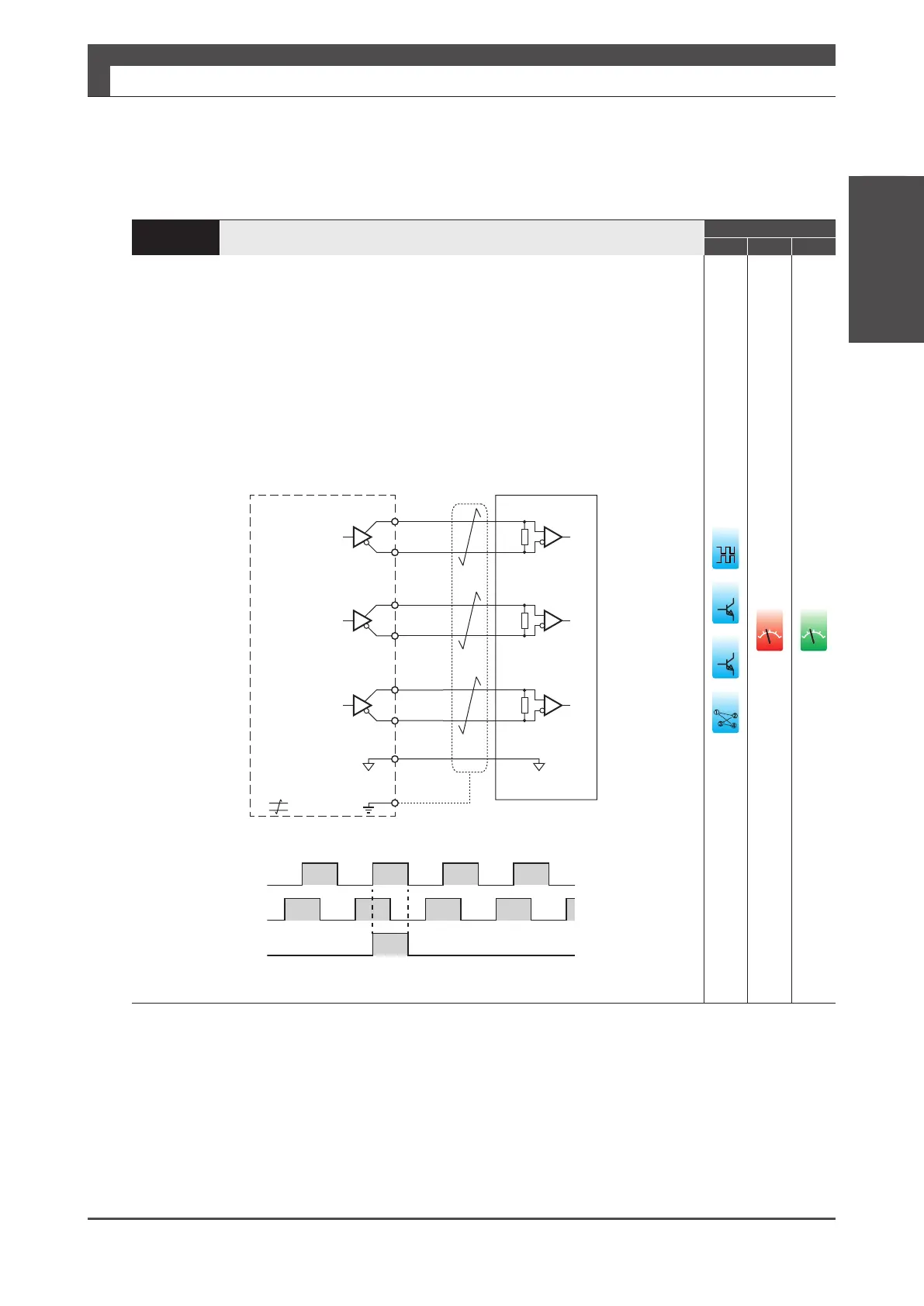
Connection to Encoder Output Circuit
Control Mode
P S T
Dierential output of encoder signal (A-phase, B-phase, Z-phase) which has been processed
with pulse division ratio.
Be sure to connect a termination resistor to the receiver circuit of the host controller.
Approximately 220 Ω (1/4W or more)
Signal ground of the communication IC in the output circuit is connected to signal ground
inside the drive.
Connect signal ground of communications IC of the host controller to Pin No.42.
Be sure to use shielded twisted-pair cable as a noise countermeasure.
SG
OutputA-phase
(RS-422)
Encodersignaloutput
SG
(OUTA)
37
(/OUTA)
38
(OUTB)
39
(/OUTB)
FG
40
(OUTB)
41
(/OUTB)
42
(SG)
220
Ω
220
Ω
220
Ω
Shield
Twisted-paircable
Drive
OutputB-phase
OutputZ-phase
Encoder Z-phase is synchronized with A-phase and output.
A
B
Z
䐟
䐠
䐡
䐢
ol
ol