24
4. Connections
Digitax SF Instruction Manual
5. Descriptions of CN1 Connector Signals
5. Descriptions of CN1 Connector Signals
1. Descriptions of CN1 Connector Signals
Icon
Control Mode
Command
Icon
Control Mode
Command
Position Control Mode
Dierential
ol
Velocity Control Mode
Analog Velocity Command
Position Control Mode
24V open collector
䐟
䐠
䐡
Velocity Control Mode
Internal Velocity Command
Position Control Mode
5V open collector
ol
Torque Control Mode
Analog Torque Command
䐟
䐠
䐡
䐢
Position Control Mode
Internal Position Command
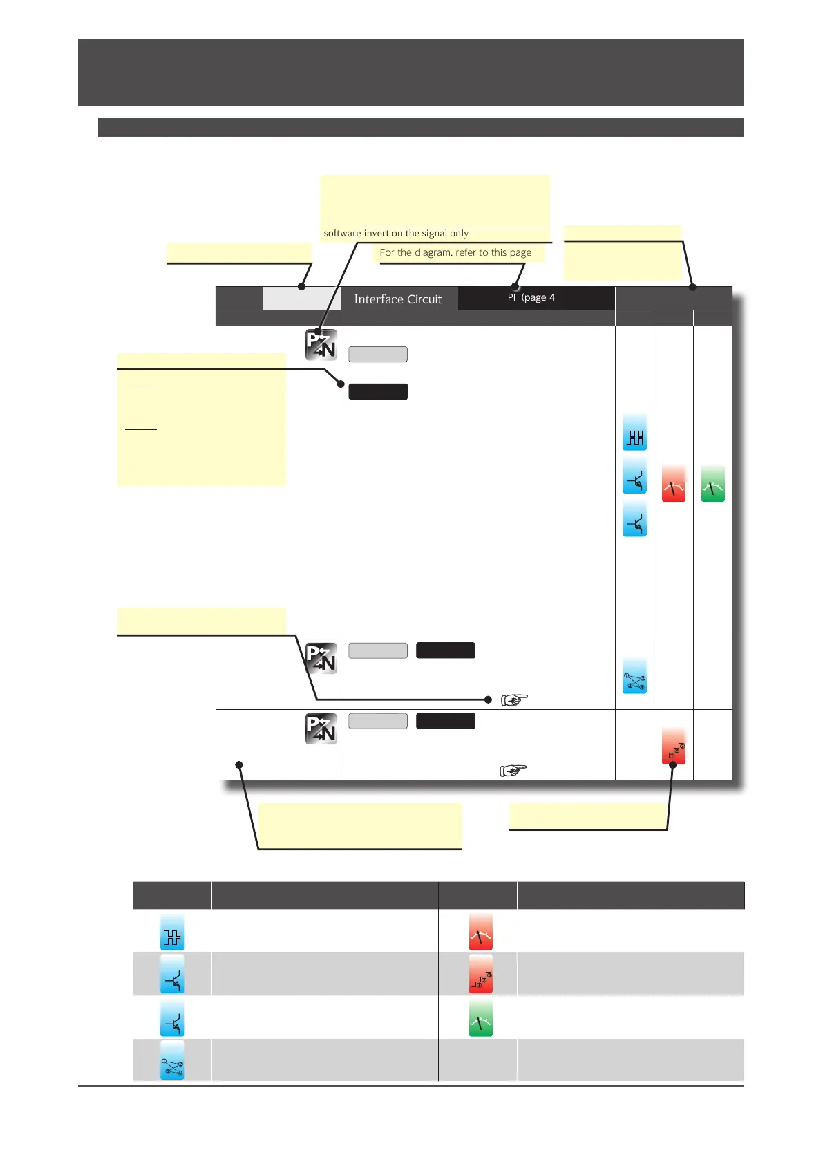
Each pin assignment of CN1 connector varies depending on the Control Mode/Command Mode.
Review the functions of each pin before using the product.
Pin No.
9
Interface Circuit
PI(page 45)
Control Mode
Signal
P S T
CCWL
CCW drive limit switch
Open
Prohibits CCW motion
Close
Allows CCW motion.
■ TIP
Make the connection such that COM- becomes open when
the equipment moves beyond the CCW motion range.
■ Related Parameters
・No.67.0
Restriction enabled when “2: Enable CCW drive limit
switch”
or “3: Enable CW/CCW drive limit switch” is selected.
・No.67.1
Enables you to specify the deceleration method. The initial
setting is 1 (short brake).
・No.67.2
Enables you to specify the status after the motor stops. The
initial setting is 0 (coast to stop).
・No.67.3
You can select keep or clear the position error counter data.
The initial setting is “0: keep”.
5
olt
olt
PCSEL3
Point No. Select 3
Open
/
Close
You can specify the Point No. with a combination of PCSEL1
…PCSEL4.
PCSEL1(Pin No.7)
䐟
䐠
䐡
䐢
VCSEL2
Speed Select 2
Open
/
Close
You can select the target speed setting with a combination
of VCSEL1…VCSEL3.
VCSEL1(Pin No.8)
䐟
䐠
䐡
Pins marked with this icon enable you to change
the input/output logic. The logic is changed on the
I/O tab of the auxiliary functions section in Digitax
SF connect. Changing the logic setting acts as a
software invert on the signal only
Related Control modes
P: Position control
V: Velocity control
T: Torque control
For the diagram, refer to this pagePin number on CN1
Reference to information about pins
with duplicated functions.
The corresponding command
mode is shown.
If the signal function varies depending on
the control or command mode selection,
all functions are listed.
Indicates signal behaviours.
Input
Open : No contact with COM-
Closed: Contact with COM-
Output
Open : Output transistor OFF
Closed: Output transistor ON

 Loading...
