39
t
T[s]
N
F[Hz]
[-]
79.0
86.0
360.0
-3dB
[Hz]
75.0
84.0
358.0
-3dB
74.0
83.0
357.0
74.0
83.0
357.0
Digitax SF Instruction Manual
Tuning
7
7. Tuning
3. Tuning Parameters
3. Tuning Parameters
Function
Apply this lter if the machine end point is still vibrating after sucient tuning was
performed and the smoothing lter was applied�
Has vibration suppression eect on mechanical systems where the vibrations don’t
appear in the torque output waveform�
When compared to the command smoothing filter, the position command filter is more
effective in reducing the absolute position error(Status No�80)�
Parameter
Filter 1 Filter 2 Filter 3
Frequency
Default:
10 [0�1 Hz]
74�0 83�0 357�0
Setting range:
10–2,000
Width
Default:
512
75�0 84�0 358�0
Setting range:
128–2,048
Depth
Default:
0
79�0 86�0 360�0
Setting range:
0–100
Remark
Increasing the notch width will make the position error large�
Too large a notch width or setting the second level notch filter will result in better
vibration suppression; however, the position
error will be larger� Set this filter
within the acceptable range of position
error.
Tuning Tip
Check the following before applying the lter
・The command from the host controller is reasonable
・The equipment is installed rmly and properly�
・The gain parameters such as inertia ratio are properly set�
・The command smoothing lters 2 (and 1) are set�
・The integral gain has been decreased and vibrations are unlikely to occur�
Start the equipment operation and apply the vibration frequency (measured at the
equipment end) to the notch frequency� If the vibration cannot be suppressed, increase
the notch width (by 800 as a rough standard)� To reduce the position error
during operation, increase the notch depth.
5 Setting List of Parameters
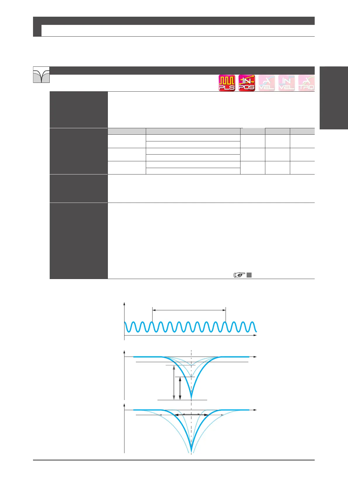
Position Command Notch Filter
Vibration frequency
Vibration frequency
Depth
[times]
Gain [dB]
Torque Command Value
or
ABS Position Error
Gain [dB]
Width