46
4. Connections
Digitax SF Instruction Manual
5. Descriptions of CN1 Connector Signals
PO
Connections to General-Purpose Output Signal
Control Mode
P S T
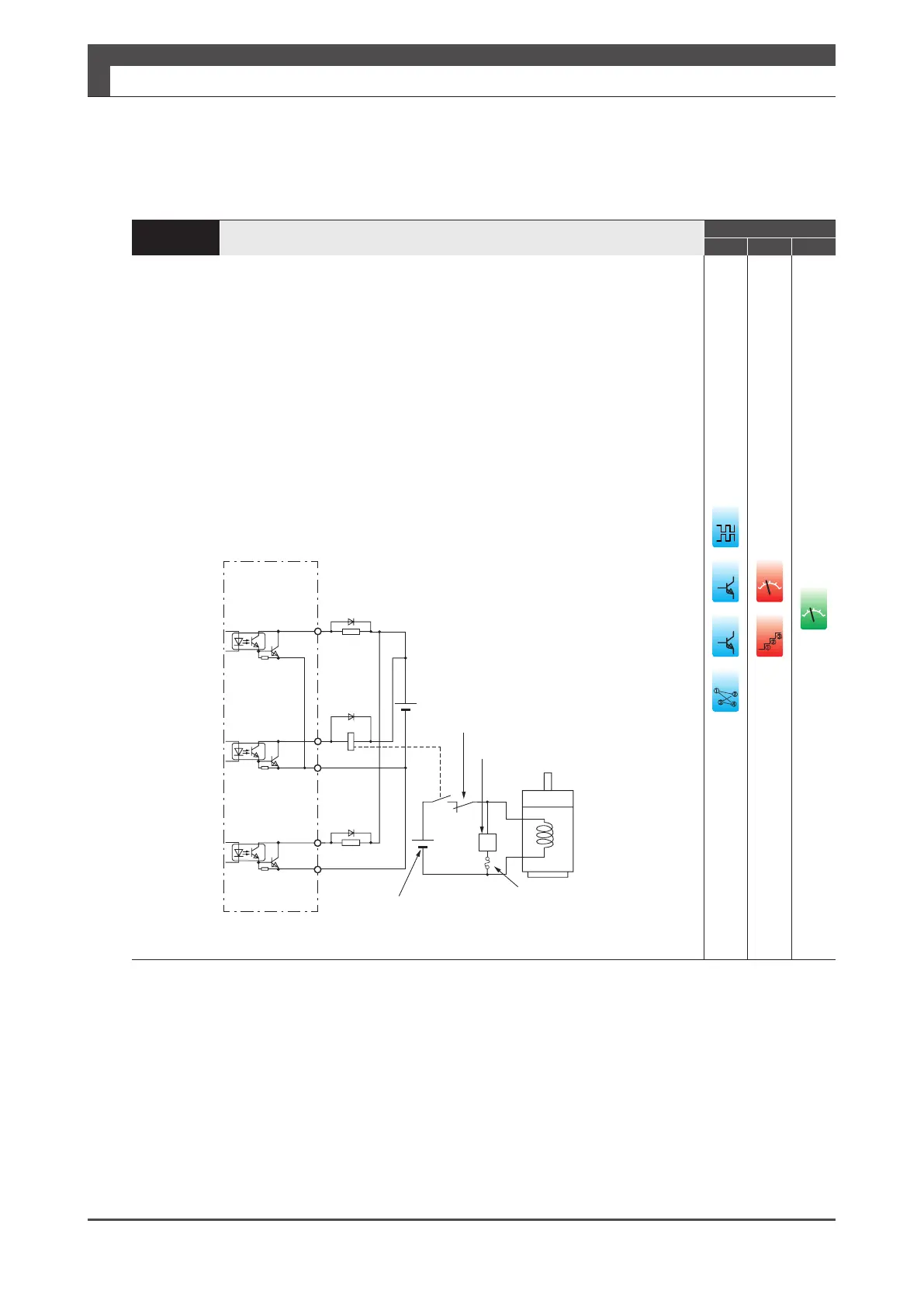
The motor brake cannot be driven directly. To drive the motor brake, be sure to use a relay.
When driving a load containing inductance component such as a relay, connect a
protection circuit (diode). Install a diode in the direction shown in the figure below.
The output circuit conguration is an open collector Darlington transistor output. Connects
to relays and optical isolators. When the transistor is on, connector-emitter voltage VCE
(SAT) is approximately 1V; a standard TTL IC does not satisfy VIL, and cannot be directly
connected.
The maximum rating of output circuit is 30V 50mA.
Pin No.13 – 18
The emitter of output transistor is common to COM- of control power.
Pin No.19, No.21
The emitter of output resistor is Pins No.20 and No.22 and independent of COM-.
MAX50mA
PinsNo.13-18
(MBRKetc.)
MAX50mA
ġ
PinsNo.19&21
(SRDY+,ALM+)
PinsNo.20&22
(SRDY−,ALM−)
őŰŸŦųġŴŶűűŭźġŧŰųġŮŰŵŰųġţųŢŬŦ
24V
RY
Fuse
(10A)
ġ
Thisiscutoffbyapromptstop.
Motor
ġ
Surgeabsorber
MAX50mA
PinsNo.13-18
(MBRKetc.)
12
ȁ
(COM−)
Loadresistor
Relaycontrol
œŦŭŢź
I/Opowersupply
Drive
24V
±10%
5
䐟
䐠
䐡
䐢
ol
i/o
䐟
䐠
ol

 Loading...
