21
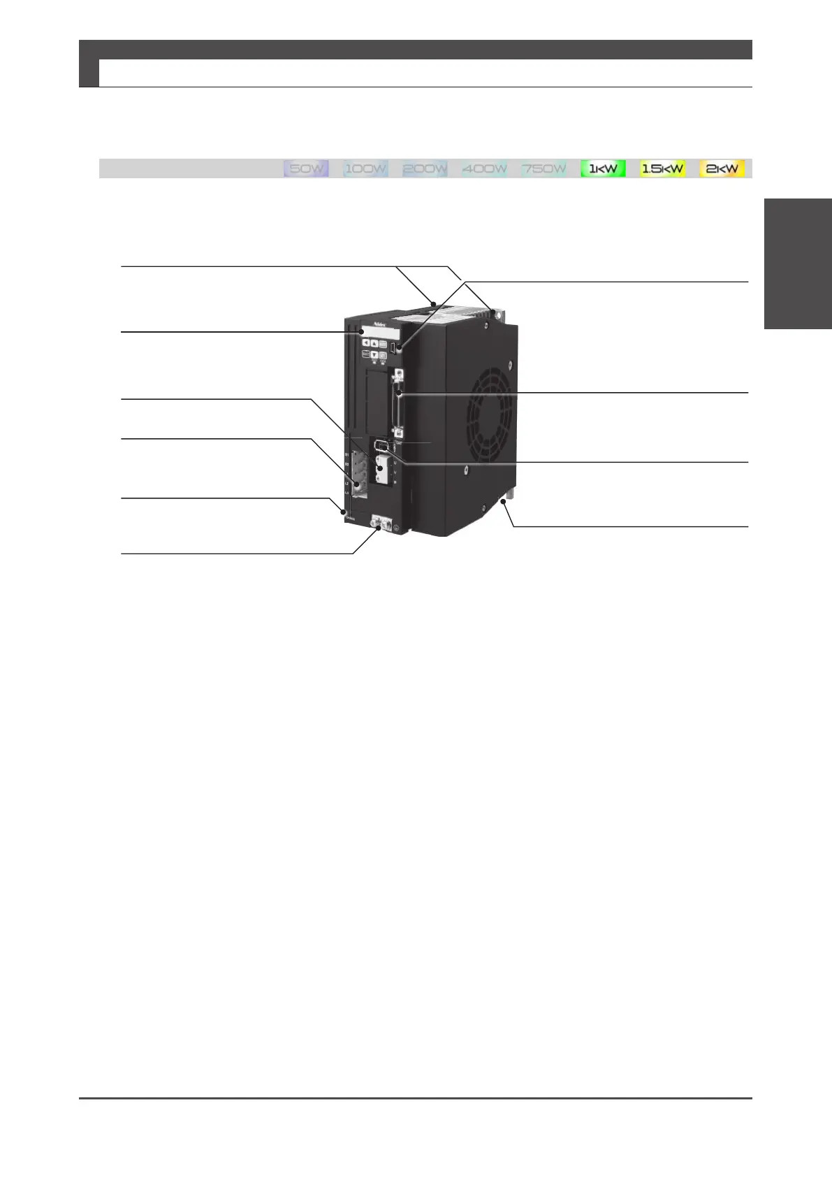
Drive:
Mounting holes
⌀ 5.5 (two locations)
The recommended screw: M5x12 mm and 8 mm, with spring washer
Setting panel
CN1 User I/O connector
Control power input, Command input,
Parallel I/O, and ABZ output
CN2 Encoder connector
Encoder connection
Mounting notch
⌀ 5.5 (one location)
The recommended screw:
M5x12 mm with spring washer
Used for parameter setting,
tuning, and status display
Motor power connector
UVW: Motor power output
Main power connection
B1 B2: Braking resistor connection
L1 L2 L3: Single-phase AC200 V
input
Hazardous voltage display LED
This will be lit while there is residual
hazardous voltage inside the drive.
Ground/Earth FG(Protective
earth) terminal
Two terminals:
M4x8 mm screw with spring washer
CN3 PC communication connector
Used for parameter settings, tuning,
and status display in the dedicated
software“Digitax SF Connect”
Digitax SF Instruction Manual
2. Specications
3. Drive
2 Specications
3. Drive
 Loading...

