3. Preparation
Digitax SF Instruction Manual
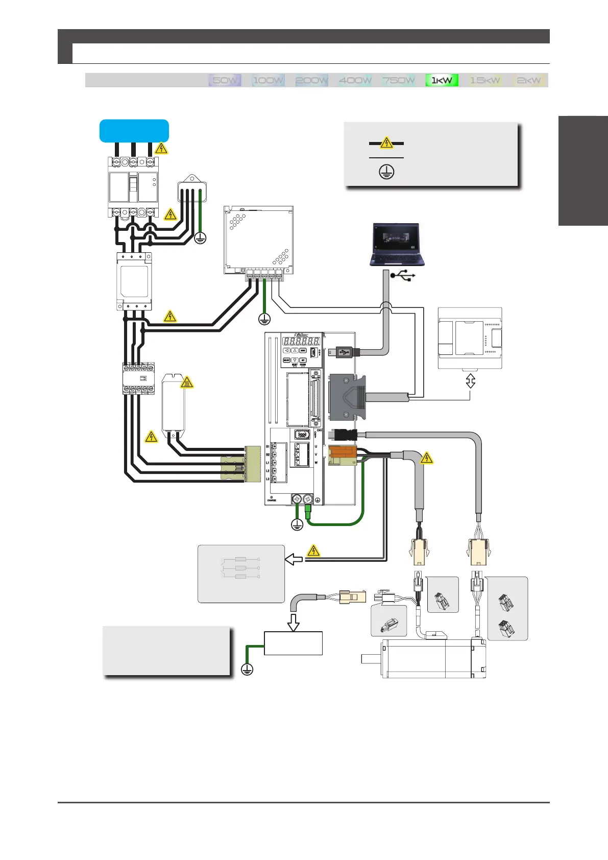
2. System Wiring
Circuitbreaker
ControlpowerDC24V
EMC noise filter
Brakingresistor
AC supplycontactor
Surgeabsorber
Digitax SF Connect
Controlsignal
Encodercable
Motorpowercable
I/Ocable
ControlpowerDC24V
HighVoltage
Non-dangerousvoltagecable
■Explanatorynotes
Groundresistance:100Ωmax.
Brakecontrolcircuit
Toconnectto
theDedicated
powersupplyunit
Powersupplyforholdingbrake
DC24V
Motorpowercable
AC Supply
Hostcontrol
equipment
■Installation,Using
Pollutiondegree2(IEC60664-1)
OvervoltageCategoryⅡ(IEC60664)
Incremental
Absolute
Brakeconnector
Motorpower
connector
Encoderconnector
L1
L2
L3
Emergency stop brakingunit
ToconnecttotheEmergency stop
brakingunit
Wiring Pattern 3
3
Preparation
2. System Wiring
For compliance with the stated EMC radio frequency emission standard the following conditions must be met:
• The specified filter must be used.
• The filter and the drive must be mounted close together on the same metal plate, ensuring direct metallic contact with the plate (the
plate must have a conductive surface, not painted or anodised). The connections between the filter and drive must be as short as
practicable.
• The screen (shield) of the motor cable must be fixed in direct contact with the same plate. The contact must be by direct contact, no
wire or 〝pigtail〟 is permitted.
• The specified ferrite core must be fitted to the signal cable(s).
• For compliance with the stated surge immunity standard the specified surge absorber must be fitted as shown in the wiring diagrams

 Loading...
