70
Specifications Section 2-2
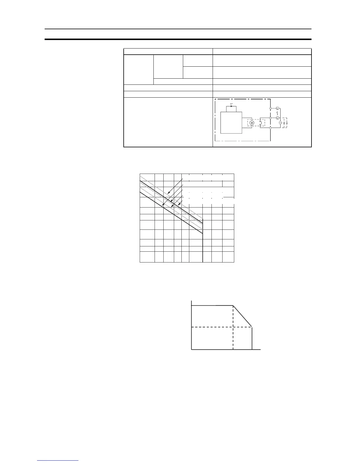
Note (1) Under the worst conditions, the service life of output contacts is as shown
above. The service life of relays is as shown in the following diagram as
a guideline.
(2) With the CPM1A-16ER/CP1W-32ER/CP1W-16ER, the load current is re-
stricted depending on the ambient temperature. Design the system con-
sidering the load current based on the following graph.
Service life
of relay
(See note.)
Electrical Resistive
load
150,000 operations (24 VDC)
Inductive
load
100,000 operations (240 VAC, cosφ = 0.4)
Mechanical 20,000,000 operations
ON delay 15 ms max.
OFF delay 15 ms max.
Circuit configuration
Item Specification
COM
OUT
OUT
Output LED
Internal
circuits
Maximum
250 VAC: 2 A
24 VDC: 2 A
300
200
100
50
30
20
5
3
2
10
0.1
0.2 0.3 0.5 0.7 1 2 3 5
Life (× 10
4
)
Contact current (A)
120 VAC resistive load
24 VDC τ = 7 ms
120 VAC cosφ = 0.4
240 VAC cosφ = 0.4
24 VDC/240 VAC resistive load
Switching rate: 1,800 operations/hou
 Loading...


