287
Inverter Positioning Section 5-3
Note (1) If inverter positioning 0 is used, pulse output 0 and PWM0 cannot be
used. If inverter positioning 1 is used, pulse output 1 and PWM1 cannot
be used.
(2) If inverter positioning 1 is used with a CPU Unit with 14 I/O Points, origin
searches cannot be used.
(3) If the continuous output mode is specified (i.e., if the number of pulses is
not specified), be sure to use the high-speed counter (linear mode) so
that it does not overflow.
High-speed Counter
Specifications for Inverter
Positioning
Note Target value matching and zone comparisons can be used for high-speed
counters with a feedback pulse input from an encoder even when using
inverter positioning.
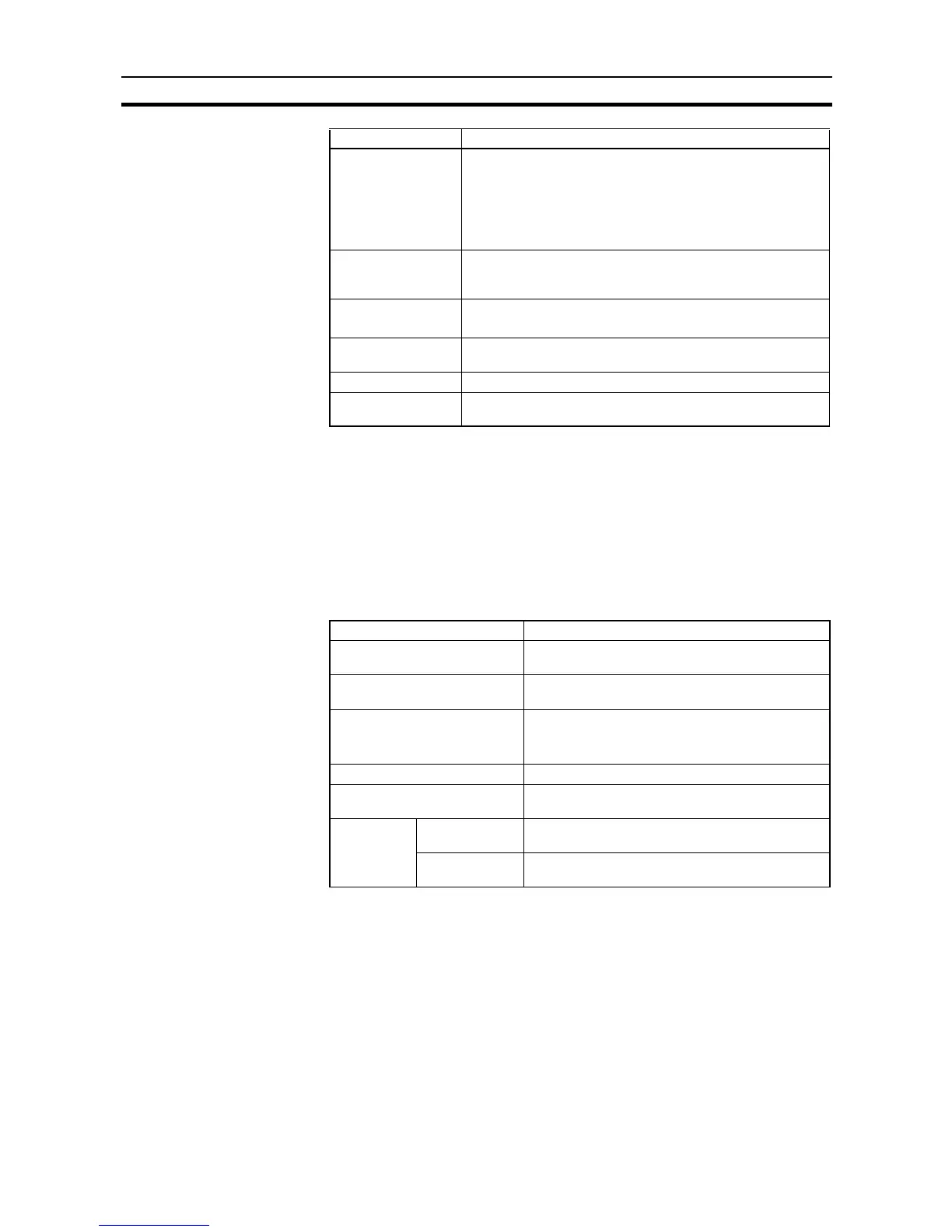
Specifications of
number of pulses
Relative positions: 0000 0000 to 7FFF FFFF hex
(2,147,483,647 incrementing and decrementing)
Absolute positions: 8000 0000 to 7FFF FFFF hex
(−2,147,483,648 to 2,147,483,647)
(Ranges of position command values and present values for
pulse output instructions)
Origin searches Motor driver and signal wire modes: 3 modes
Origin search modes: 2 modes
Origin detection methods: 3 methods
Feedback pulse
input ports
High-speed counter 0 and high-speed counter 1 (fixed)
Maximum response frequency: 100 kHz (J models: 20kHz)
Present value range
for feedback pulses
32 bits: 8000 000 to 7FFF FFFF hex
Error counter range 8000 to 7FFF hex (signed)
Error counter calcu-
lation cycle
4 to 1,020 ms (x4)
Item Specification
Item Specification
Response frequency and num-
ber of counters
Two 2-phase counters at 50 kHz and two single-
phase counters at 100 kHz
Counting mode Differential-phase inputs (x4), up/down pulse
inputs, or pulse plus direction inputs
Numeric range mode Linear mode
Note Always set linear mode when using inverter
positioning.
Numeric range 32 bits (−2,147,483,648 to 2,147,483,647)
Reset method Phase Z signal (reset input) + software reset, or
software reset
Interrupts
(See note.)
Ta r g et va l ue
matching
Up to 48 target values and interrupt task numbers
can be registered.
Zone compari-
son
Up to 8 sets of upper values, lower values, and
interrupt task numbers can be registered.