8
Features and Main Functions Section 1-1
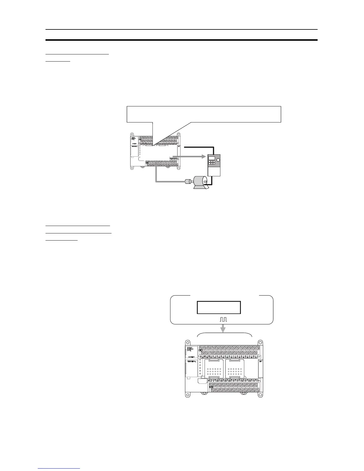
Positioning with an
Inverter
Positioning can be controlled using an inverter. Previously, an internal pulse
output with trapezoidal acceleration/deceleration is created using the PULSE
OUTPUT instruction. The position offset is calculated using an error counter
for the feedback pulse input from a rotary encoder connected to an inductive
motor and the internal pulse output. The error counter is then used to output a
speed command to the inverter to control positioning. This enables positioning
with high-capacity motors, as well as low-cost positioning with small-capacity
motors (in comparison to using a servo).
Note If high-precision positioning is required, we recommend using an inverter with
vector control.
Full Complement of
High-speed Counter
Functions
High-speed counter inputs can be enabled by connecting rotary encoders to
the built-in inputs. The ample number of high-speed counter inputs makes it
possible to control a multi-axis device with a single PLC.
• Four 100-kHz (single phase)/50-kHz (differential phases) high-speed
counter inputs (4 counters/2 axes) are provided as a standard feature.
(See note.)
• For CP1L-J PLCs, four 20-kHz (single phase)/10-kHz (differential phases)
high-speed counter inputs (4 counters/2 axes) are provided as a standard
feature. (See note.)
Note Settings in the PLC Setup determine whether each input point is to
be used as a normal input, interrupt input, quick-response input, or
high-speed counter.
A virtual pulse output is created using a pulse output instruction, the position
offset is calculated using an error counter, and a frequency (i.e., speed)
command is output according to the position offset to control positioning.
Analog output or RS-422A (Modbus-RTU)
Frequency
command
Pulse input
Encoder
Pulse Output
Instruction
Inverter
Motor
24 built-in inputs
(Functions can be assigned.)
High-speed counters
(4 counters/2 axes)
100 kHz (single phase)