456
Analog I/O Units Section 7-4
Note Word (n + 1) can be used for either the range code or the analog output set
value.
Connecting the Analog I/O
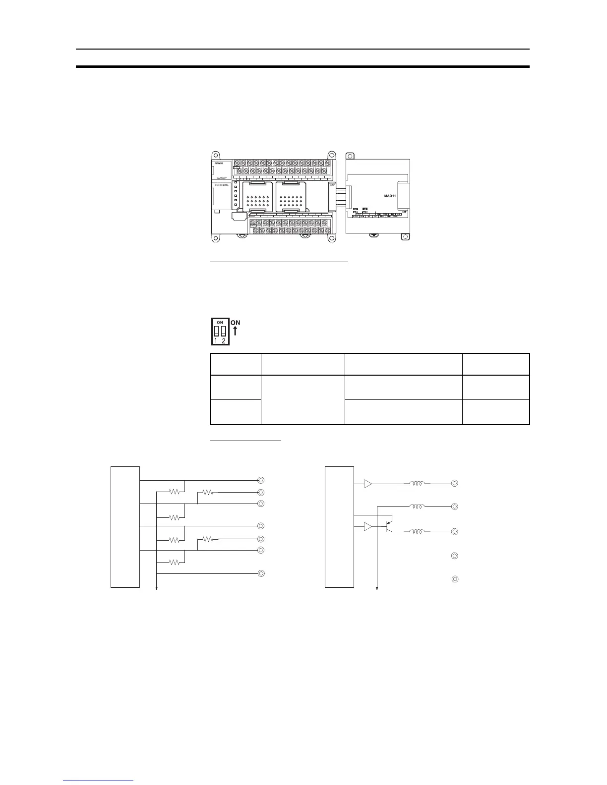
Unit and Setting the DIP
Switch
This section describes how to connect an Analog I/O Unit to the CPU Unit.
Setting the Averaging Function
DIP switch pins 1-1 and 1-2 are used to set the averaging function. When
averaging is enabled, a moving average of the last eight input values is output
as the converted value. The averaging function can be set separately for ana-
log inputs 1 and 2.
Wiring Analog I/O Devices Internal Circuits
DIP switch
pin
Function Setting Default
1-1 Averaging Analog input 0
OFF: Disabled; ON: Enabled
OFF
1-2 Analog input 1
OFF: Disabled; ON: Enabled
OFF
SYSMAC
CP1L
L1 L2/N
COM 01 03 05 07 09 11 01 03 05 07 09 11
00 02 04 06 08 10 00 02 04 06 08
10
00 01 02 03 04 06 00 01 03 04 06
COM COM COM COM 05 07 COM 02 COM 05
07
IN
OUT
NC
NC
CPU Unit
CP1W-MAD11
CPM1A-MAD11
Analog I/O Unit
Analog Inputs Analog Outputs
Analo