684
Connections to Serial Communications Option Boards Appendix F
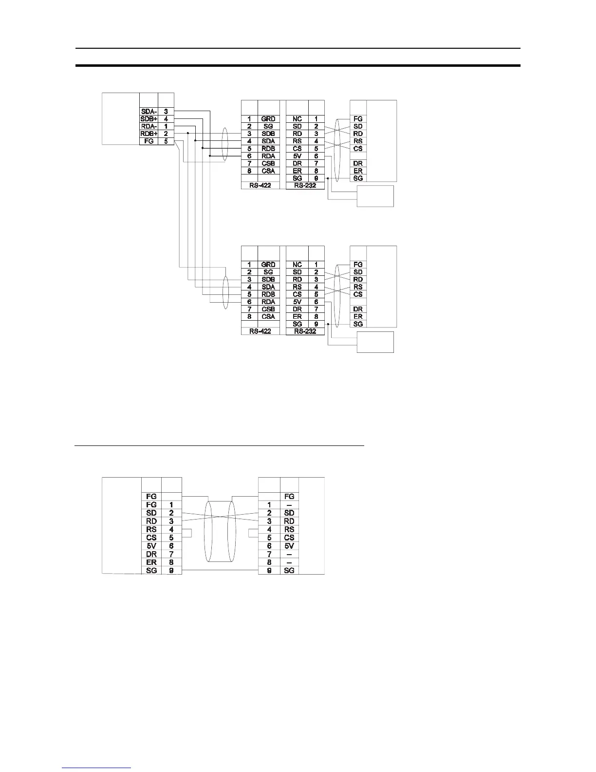
1:N NT Link Connections with Programmable Terminals
Direct Connections from RS-232C to RS-232C Ports
• Communications Mode: Host Link (unit number 0 only for Host Link)
NT Link (1:N, N = 1 Unit only)
• OMRON Cables with Connectors:
XW2Z-070T-1: 0.7 m
XW2Z-200T-1: 2 m
RS-422A/
485 Option
Board
Pin
Signal
CPU Unit
D-sub, 9-pin con-
nector (male)
4-wire
Terminating
resistance ON
Signal
Shield
D-sub, 9-pin
connector
(male)
DIP Switch
Pin 1: ON
Pin 2: ON (terminating
resistance)
Pin 3: OFF
Pin 4: OFF
Pin 5: OFF
Pin 6: ON
Terminal block
(+) 5-V
(-) power
RS-232C
Interface
Signal
Shield
Signal PinPin Signal
NT-AL001-E Link Adapter
NT-AL001-E Link Adapter
Shield
(+) 5-V
(-) power
RS-232C
Interface
Terminal block
Shield
DIP Switch
Pin 2: OFF,
otherwise
same as below.
Signal PinPin Signal
RS-232C
RS-422A
RS-232C
CPU Unit
PinSignal
PT
D-sub, 9-pin
connector (male)
RS-232C
Interface
Hood
Hood
D-sub, 9-pin
connector (male)
RS-232C
Option
Board
Pin Signal