53
Specifications Section 2-2
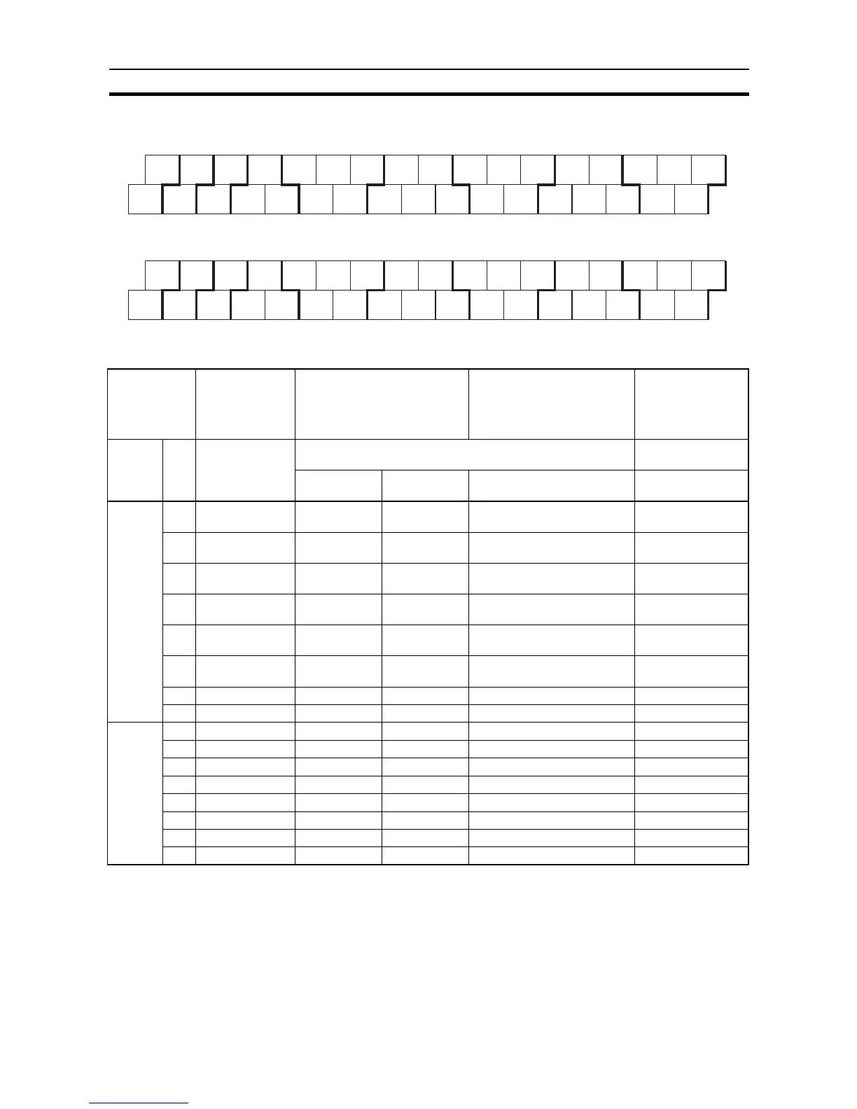
Output Terminal Block (Bottom Block)
Setting Output Functions Using Instructions and PLC Setup
Address When the
instructions to
the right are not
executed
When a pulse output
instruction (SPED, ACC,
PLS2, or ORG) is executed
When origin searches are
enabled in the PLC Setup,
and an origin search is
executed with ORG
instruction
When the PWM
instruction is
executed
Word Bit Normal outputs Fixed duty ratio pulse output Variable duty ratio
pulse output
CW/CCW Pulse plus
direction
+ When the origin search
function is used
PWM output
CIO 100 00 Normal output 0 Pulse output 0
(CW)
Pulse output 0
(pulse)
--- ---
01 Normal output 1 Pulse output 0
(CCW)
Pulse output 0
(direction)
--- PWM output 0
02 Normal output 2 Pulse output 1
(CW)
Pulse output 1
(pulse)
--- ---
03 Normal output 3 Pulse output 1
(CCW)
Pulse output 1
(direction)
--- PWM output 1
04 Normal output 4 --- --- Origin search 0 (Error counter
reset output)
---
05 Normal output 5 --- --- Origin search 1 (Error counter
reset output)
---
06 Normal output 6 --- --- --- ---
07 Normal output 7 --- --- --- ---
CIO 101 00 Normal output 8 --- --- --- ---
01 Normal output 9 --- --- --- ---
02 Normal output 10 --- --- --- ---
03 Normal output 11 --- --- --- ---
04 Normal output 12 --- --- --- ---
05 Normal output 13 --- --- --- ---
06 Normal output 14 --- --- --- ---
07 Normal output 15 --- --- --- ---
AC Power Supply Models
DC Power Supply Models
00 01 02 04 05 07 00 02 04 05 07 00 02 04 05 07
COM COM COM 03 COM 06 COM 01 03 COM 06 COM 01 03 COM 06
CIO 100 CIO 101 CIO 102
00 01 02 04 05 07 00 02 04 05 07 00 02 04 05 07
COM COM COM 03 COM 06 COM 01 03 COM 06 COM 01 03 COM 06
CIO 100 CIO 101 CIO 102
00
COM
NC
NC
+
−