63
Specifications Section 2-2
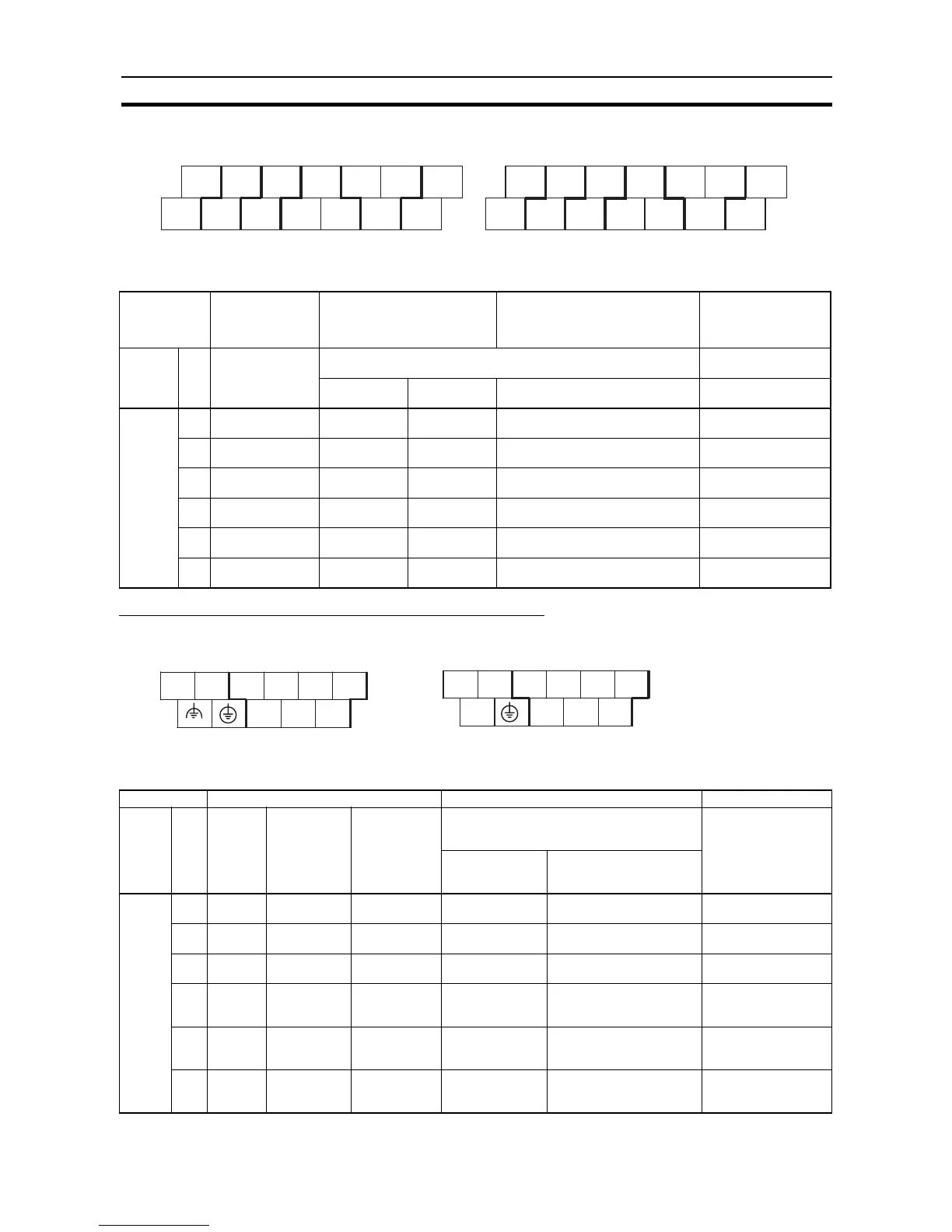
Output Terminal Block (Bottom Block)
Setting Functions Using Instructions and PLC Setup
I/O Terminal Blocks of CPU Units with 10 I/O Points
Input Terminal Block (Top Block)
Setting Input Functions Using PLC Setup
Address When the
instructions to
the right are not
executed
When a pulse output
instruction (SPED, ACC,
PLS2, or ORG) is executed
When origin searches are
enabled in PLC Setup, and an
origin search is executed with
ORG instruction
When the PWM
instruction is
executed
Word Bit Normal outputs Fixed duty ratio pulse output Variable duty ratio
pulse output
CW/CCW Pulse plus
direction
+ When the origin search
function is used
PWM output
CIO 100 00 Normal output 0 Pulse output
0 (CW)
Pulse output
0 (pulse)
--- ---
01 Normal output 1 Pulse output
0 (CCW)
Pulse output
0 (direction)
--- PWM output 0
02 Normal output 2 Pulse output
1 (CW)
Pulse output
1 (pulse)
--- ---
03 Normal output 3 Pulse output
1 (CCW)
Pulse output
1 (direction)
--- PWM output 1
04 Normal output 4 --- --- Origin search 0 (Error counter
reset output)
---
05 Normal output 5 --- --- Origin search 1 (Error counter
reset output)
---
Address Input operation settings High-speed counters Origin searches
Word Bit Normal
inputs
Interrupt
inputs
(See note.)
Quick-
response
inputs
Operation settings:
High-speed counters enabled
Phase-Z reset
Origin searches
enabled for pulse
outputs 0
Single-phase
(increment
pulse input)
Two-phase (differential
phase x4, up/down, or
pulse/direction)
CIO 0 00 Normal
input 0
--- --- Counter 0, incre-
ment input
Counter 0, A phase, up,
or count input
---
01 Normal
input 1
--- --- Counter 1, incre-
ment input
Counter 0, B phase,
down, or direction input
---
02 Normal
input 2
--- --- Counter 2, incre-
ment input
Counter 1, A phase, up,
or count input
---
03 Normal
input 3
--- --- Counter 3, incre-
ment input
Counter 1, B phase,
down, or direction input
Pulse output 0: Ori-
gin proximity input
signal
04 Normal
input 4
Interrupt
input 0
Quick-
response
input 0
Counter 0,
phase-Z/reset
input
Counter 0, phase-Z or
reset input
---
05 Normal
input 5
Interrupt
input 1
Quick-
response
input 1
Counter 1,
phase-Z reset
input
Counter 1, phase-Z or
reset input
Pulse output 0: Ori-
gin input signal
COM
05
AC Power Supply Models
DC Power Supply Models
COM
+
−
NC
CIO 100
NC
COM COM 03
COM
CIO 100
COM
COM
01 0400 02
COM
03
0501 0400 02
NC
NC
NC
NC
L1 L2/N
COM
01 03 05
00 02 04
AC Power Supply Models
Inputs (CIO 0)
DC Power Supply Models
COM
01 03 05
00 02 04
+
−
NC
Inputs (CIO 0)