65
Specifications Section 2-2
Note (1) HIgh-speed counter inputs, interrupt inputs, and quick-response inputs
can also be used as normal inputs.
(2) The bits that can be used depend on the model of CPU Unit.
(3) The response time is the hardware delay value. The delay set in the PLC
Setup (0 to 32 ms, default: 8 ms) must be added to this value.
High-speed Counter Inputs
OFF delay 2.5 µs max. 50 µs max. 1 ms max. (See note 3.)
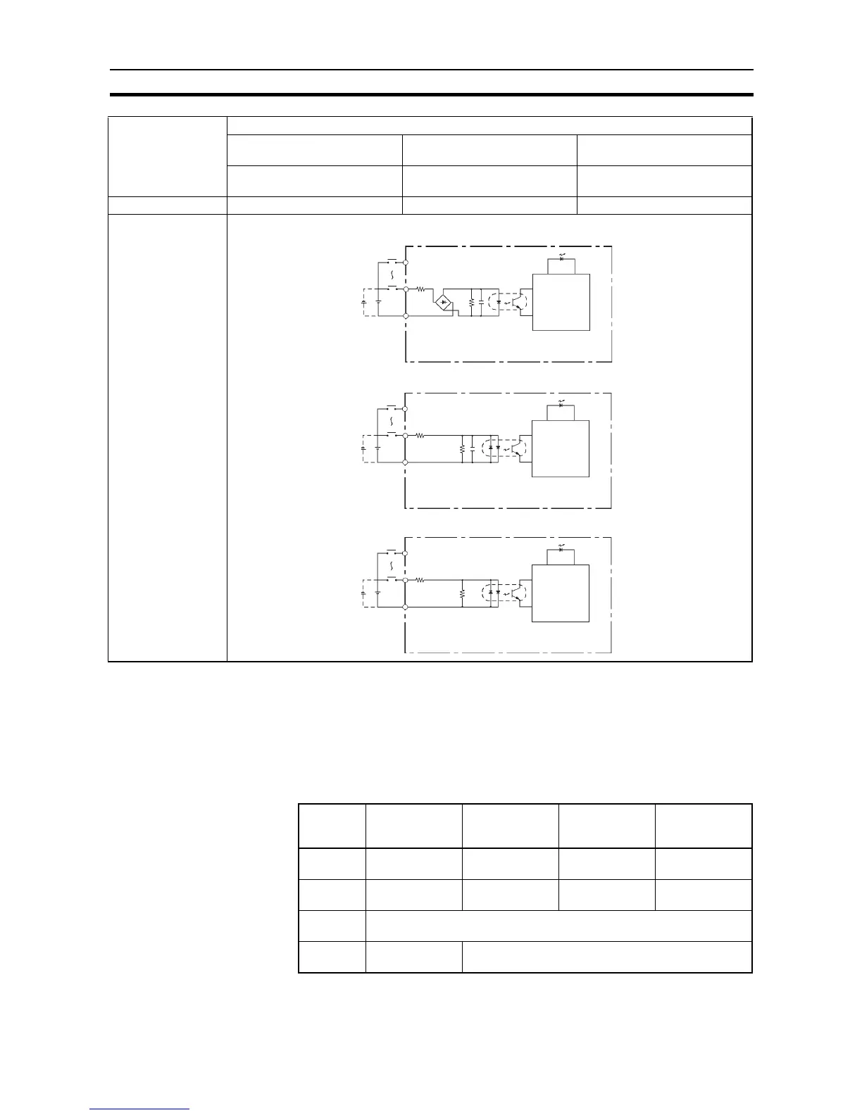
Circuit configuration
Item Specification
High-speed Counter Inputs Interrupt Inputs and
Quick-response Inputs
Normal inputs
CIO 0.00 to CIO 0.03 CIO 0.04 to CIO 0.09 (See
note 1.)
CIO 0.10 to CIO 0.11 and
CIO 1.00 to 1.11 (See note 2.)
IN
IN
COM
3.0 kΩ
4.3 kΩ
1000 pF
3.0 kΩ
1000 pF
IN
IN
COM
910 Ω
IN
IN
COM
4.7 kΩ
750 Ω
Input bits: CIO 0.04 to CIO 0.11
Input bits: CIO 0.00 to CIO 0.03, CIO 1.00 to CIO 1.03
Input bits: CIO 1.04 to CIO 1.11
Input LED
Input LED
Input LED
Internal
circuits
Internal
circuits
Internal
circuits
Bit Differential
phase mode
Pulse plus
direction input
mode
Up/down input
mode
Increment
mode
CIO 0.00,
CIO 0.02
A-phase pulse
input
Pulse input Increment pulse
input
Increment pulse
input
CIO 0.01,
CIO 0.03
B-phase pulse
input
Direction input Decrement
pulse input
Normal input
CIO 0.04,
CIO 0.05
Z-phase pulse input or hardware reset input (Can be used as ordinary
inputs when high-speed counter is not being used.)
Max. count
frequency
50 kHz (4×)100 kHz