PART 1: CX-Programmer
CHAPTER 4 – Reference OMRON
CX-Programmer _Page 72
Use the following procedure to apply automatic allocation.
1, 2, 3…
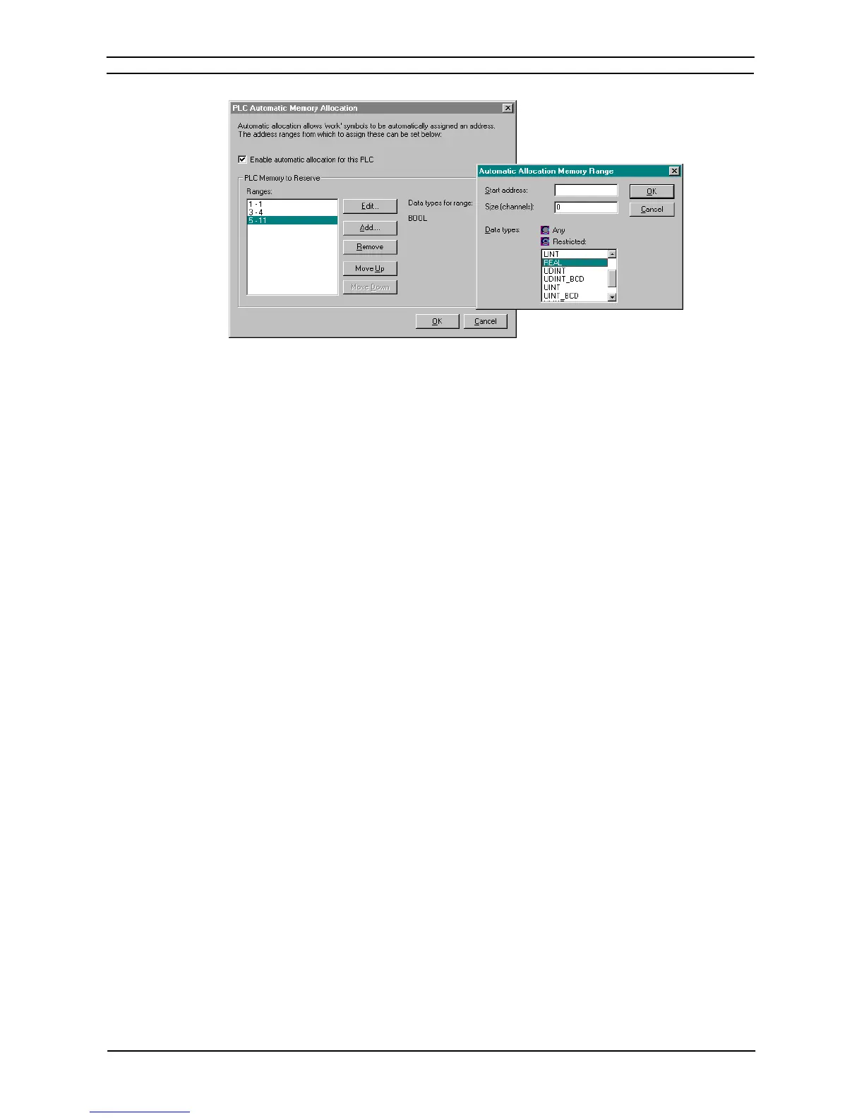
1. Select (tick) the Enable automatic allocation for this PLC option.
A list of memory ranges may be entered for the PLC. The list is ordered, so that the first
area in the list is allocated first.
2. Use the Add... button to add an area to the allocation list. A dialog is shown to input the
details for the area:
3. Type in the Start address and Size (channels) to define the address range in the PLC for
CX-Programmer to allocate from.
4. Choose one or more data types that are to be allocated in this area. By default, all
applicable data types will be allocated from within this area. A restriction can be made, so
that for example, a separate memory area can be set to allocate BOOLs and CHANNELs.
5. Use the Remove button to remove the selected allocation range from the list.
6. Use the Move Up and Move Down buttons to move a selected range up and down in the
priority order for the PLC.
Note: CJ2 CPU Units, we recommend that you use the required number of banks from the highest
bank numbers for automatic allocation.
• Either one or two automatic allocation areas can be set. Any area with continuous
addresses is counted as one area. (For example, the addresses in E0_0 to E0_32767 and
E1_0 to E1_32767 are continuous, and so they could be set together as one area.)
• To use force-setting/resetting, you must set words in the EM Area for which force-
setting/resetting is supported.
With CJ2H CPU Units with unit version 1.2 or later or CJ2M Units, PLC - Memory
Allocation - EM Memory Settings can be used to specify the EM Area banks for which bits
can be force-set/reset. (The first bank is specified and force-setting/resetting bits is possible
in that bank and all banks following it.) This is called the EM Area force-setting/resetting
function. Refer to the note on page 14 of CX-Server PLC Tools for details.
• Automatic allocation cannot be set if part of the EM Area is converted to trace memory or
file memory using PLC - Memory Allocation - EM Memory Settings.
Note: With CJ-series CJ2 CPU Units, an error will occur if an address within the range set as the
reserved PLC memory area for automatic PLC address allocation is input directly.
• The address will be displayed in red in the ladder view.
• In the program check, a message will be displayed indicating that an error occurred
because operand x is out of range.
Note: The status of the EM Area is held when the power supply is turned back ON or the operating
mode is changed. Be careful if you use BOOL data in the EM Area for inputs in the program.
Allocation of Symbols
Symbols can be defined to use automatic allocation simply by leaving their addresses blank. CX-Programmer
then allocates the symbol address during compilation. The actual address allocated is shown against the symbol,
but the address is marked as ‘Auto’ to show that the address has not been assigned by the user.