PART 2: CX-Server PLC Tools
OMRON CHAPTER 10 – Data Links
CX-Server PLC Tools_ Page 99
Note 1: It is possible to add or delete nodes from the participating data link nodes (1) using the
Datalink Wizard.
Adding nodes
Select
Table | Add Source Link.
Add
Adding link words
Select
Table | Add Destination.
Deleting specified nodes or link areas Select the node from the node list, and
then click
F8: Delete Node.
Delete
Deleting link areas from specified nodes Select the node from the table, and then
click
F8: Delete Node.
Note 2: It is possible to change the following items set by the Datalink Wizard for each node:
(2) PLC type, (3) Area (memory area and start address), (4) Send size, (5) Node refresh
sequence (see note 3), and (6) Status area.
Note 3: The node refresh sequence is set using F4: Move Up Area and F5: Move Down Area.
Reference: The operations differ for Controller Link and SYSMAC LINK when creating data links.
The following table shows the points on which the manually set data link functions are
different.
Function Controller Link SYSMAC LINK
(1) Offset setting Supported Not supported
(2) Receive size setting Supported Not supported. (It is only possible
to specify whether all of none of
the data sent is to be received.)
(3) Memory area Area 1: Can be selected.
Area 2: Can be selected.
(CIO, LR, DM, EM, etc.,
according to PLC type)
Area 1: CIO
Area 2: DM
(Fixed.)
(4) Communications cycle time
setting
Not supported Supported
These four differences apply even to data link setup operations using the CX-Net. Aside from these points, other
operations are basically the same.
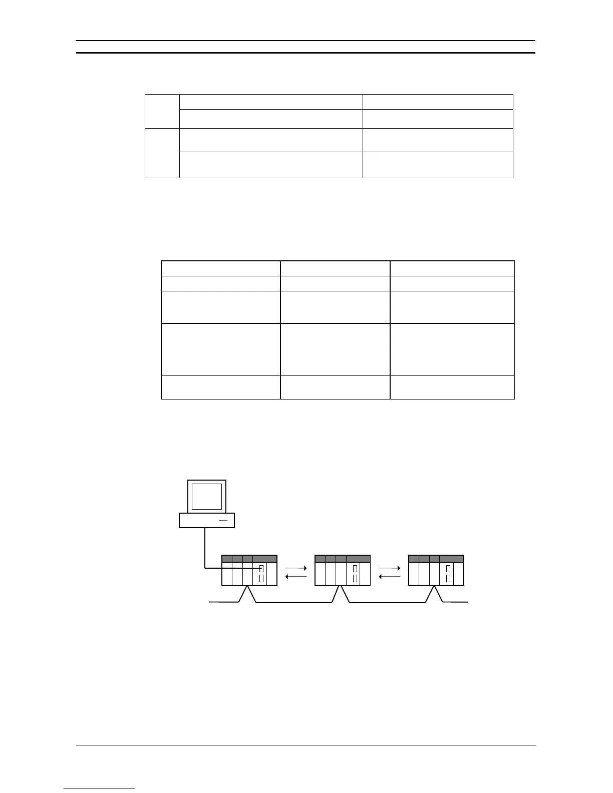
System Configuration Example
The procedure is described below, from data link creation through startup, taking a Controller Link data link
system as an example.
CX-Net
Controller Link network
CS1G-CPU45
Peripheral Bus or Host Link
Data link
CS1G-CPU45 C200HX
1 2 3
Data link
PLC type
Node address