PART 2: CX-Server PLC Tools
CHAPTER 10 – Data Links OMRON
CX-Server PLC Tools_Page 96
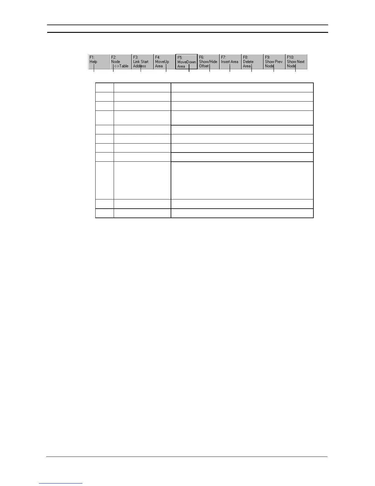
Function Bar
(1)
(2) (3)
(4)
(5) (6)
(7) (8)
(9)
(10)
No. Icon Function
(1) F1: Help Displays help.
(2) F2: Node<->Table Moves the focus between nodes and tables.
(3) F3: Link Start Address Moves the focus between settings for the link start addresses
(status, Area 1, Area 2).
(4) F4: Move Up Area Moves a node up the node refresh sequence.
(5) F5: Move Down Area Moves a node down the node refresh sequence.
(6) F6: Show/Hide Offset Shows or hides the offset for the node being displayed.
(7) F7: Insert Area Inserts a new receive area (new node).
(8) F8: Delete Node Deletes a node or communications area.
To delete a node or link area from a node list, select the item from
the list and then click F8: Delete Node.
To delete a node or link area from a table, select the item from the
table and then click F8: Delete Node.
(9) F9: Show Prev Node Shows the previous node.
(10) F10: Show Next Node Shows the next node.
Manually Setting Data Links
Follow the procedure described below to create data link tables manually for Controller Link or SYSMAC LINK
data links.
Note: There is no need to create a data link tables when data links are set automatically. For
details on automatic setup, refer to Automatically Set Data Links.