PART 2: CX-Server PLC Tools
CHAPTER 10 – Data Links OMRON
CX-Server PLC Tools_Page 92
Automatic Settings
Automatic settings can be used for simple data exchanges involving fixed allocations, when all nodes are set for
the same send size and the same data is to be shared among all nodes in order of node address.
Using a Programming Device (such as the CX-Programmer or a Programming Console), set the data exchange
method in the DM parameter area of the startup node.
Controller Link
Note: The following table provides a general comparison of automatic setup between
Controller Link and SYSMAC Link.
Item Controller Link SYSMAC LINK
Node sequence Fixed at ascending order.
Receive-only nodes Not supported.
Send-only nodes Not supported.
Memory area Can be specified. (Area 1: CIO Area
or LR Area; Area 2: DM Area or EM
Area)
Cannot be specified. Fixed as
follows:
CS/CJ/CV Series: Area 1: CIO;
Area 2: DM
C Series: Area 1: LR; Area 2: DM
Start address Can be specified. Cannot be specified.
Send size Same size for all nodes can be
specified.
Same size for all nodes can be
selected from specific patterns.
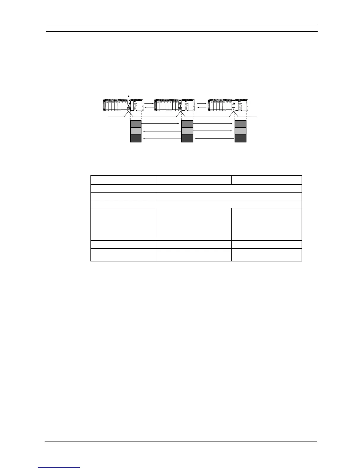
This section describes how to perform Controller Link and SYSMAC LINK operations from creating data link
tables to starting up the data links.
PLC PLC PLC
Controller Link
Unit
Data exchange (shared data)
(I/O Area, LR Area, DM Area, etc.)